Driving mechanism for liquid crystal based optical device

a technology of liquid crystal based optical devices and driving mechanisms, which is applied in static indicating devices, non-linear optics, instruments, etc., can solve the problems of increasing the cost of an optical device employing the analog dac method, and achieves the effects of less costly parts, less expensive components, and simple design of optical devices

Inactive Publication Date: 2011-01-06
AVANEX CORP
View PDF7 Cites 43 Cited by
  • Summary
  • Abstract
  • Description
  • Claims
  • Application Information

AI Technical Summary

Benefits of technology

Embodiments of the present invention provide an optical device with LC cells that employs a digital technique to drive the LC cells. When compared with the analog DAC method, the digital technique for driving the LC cells allows the optical device to be simpler in design and more scalable, and employ less costly parts to achieve comparable resolution.

Problems solved by technology

As the number of wavelength channels increases, the cost of an optical device employing the analog DAC method increases correspondingly.

Method used


Image

  • Driving mechanism for liquid crystal based optical device
  • Driving mechanism for liquid crystal based optical device
  • Driving mechanism for liquid crystal based optical device

Examples


Embodiment Construction

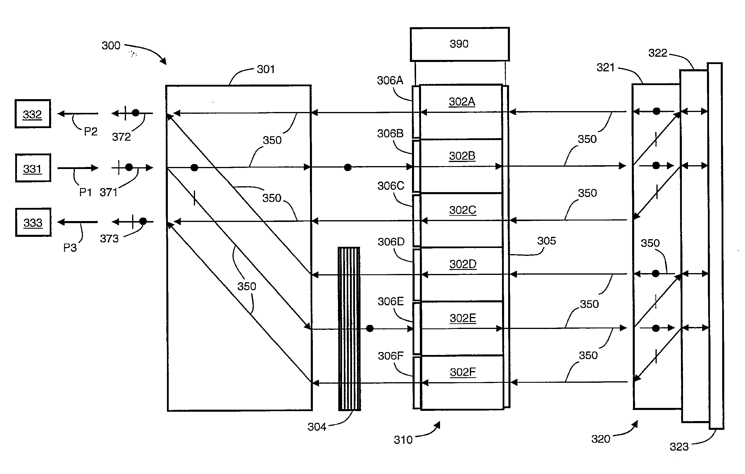
FIG. 3 schematically illustrates a cross-sectional view of an optical device 300 having LC cells that employ a digital technique to drive the LC cells. Optical device 300 includes a birefringent displacer 301, an LC assembly 310, a polarization separating and rotating assembly 320, and a half-wave plate 304, all of which are optically coupled as shown for the treatment, i.e., the switching and attenuation, of an input beam 371. To act as a 1×2 optical switch, optical device 300 is optically coupled to an input port 331 and output ports 332, 333 by optical paths P1, P2, and P3, respectively. The possible optical paths 350 of input beam 371, output beams 372, 373, and their respective s- and p-polarized components in optical device 300 are depicted as arrows. P-polarized light is denoted by a vertical bar, and s-polarized light by a dot.

Birefringent displacer 301 may be a YVO4 crystal or other birefringent material that translationally deflects incident light beams by different amount...


PUM

PropertyMeasurementUnit
voltageaaaaaaaaaa
voltageaaaaaaaaaa
frequencyaaaaaaaaaa

Abstract

An optical device with liquid crystal (LC) cells for conditioning the polarization of incident light includes a drive unit for the LC cells that employs a digital technique. According to this digital technique, the drive unit generates control signals for opposing electrodes of the LC cells based on digital signals that have the same period but differ in phase by up to one-half period. By employing digital signals that differ in phase by up to one-half period with high resolution, the differential voltage across the LC cells can be controlled precisely to a desired RMS value.

Description

BACKGROUND OF THE INVENTION1. Field of the InventionEmbodiments of the present invention relate generally to optical communication systems and components and, more particularly, to a driving mechanism for a liquid crystal-based optical device.2. Description of the Related ArtLiquid crystal (LC) based optical devices are known in the art, and in some applications, offer significant advantages over other optical device designs. In an LC based optical device, LC cells are used to rotate the polarization of incident light. By controlling the polarization, other optical elements, such as birefringent materials and wave plates, can be employed to direct light according to orthogonal polarization states. U.S. patent application Ser. No. 12 / 014,730, filed Jan. 15, 2008 and U.S. patent application Ser. No. 12 / 392,800, filed Feb. 25, 2009, both of which are incorporated by reference herein, describe optical switches that employ LC cells for rotating the polarization of incident lightA twisted...

Claims


Application Information

Patent Timeline
Patent Type & Authority Applications(United States)
IPC IPC(8): G02F1/1335
CPCG02F1/31G09G3/36G09G3/001
Inventor DAHL, SCOTT R.
Owner AVANEX CORP
Why Eureka
Try Eureka