Method of operating a resonant power converter and a controller therefor

a technology of resonant power converter and controller, which is applied in the direction of electric variable regulation, process and machine control, instruments, etc., to achieve the effect of reducing or eliminating the requirement for discrete steps in power and improving the control of the switching period

Active Publication Date: 2011-01-06
NXP BV
View PDF22 Cites 30 Cited by
  • Summary
  • Abstract
  • Description
  • Claims
  • Application Information

AI Technical Summary

Benefits of technology

[0009]It is an object of the present invention to allow improved control of the swit...

Problems solved by technology

Further, there may be a second delay between opening the second switch and cl...

Method used


Image

  • Method of operating a resonant power converter and a controller therefor
  • Method of operating a resonant power converter and a controller therefor
  • Method of operating a resonant power converter and a controller therefor

Examples


Embodiment Construction

ation of a power converter operating in normal or high power mode;

[0033]FIG. 13 is a state plane representation of a power converter operating in a low power mode;

[0034]FIG. 14 is a state plane representation of a converter operating in a low power mode including energy dump, in accordance with embodiment of the invention, and,

[0035]FIG. 15 shows waveforms of a converter including an energy dump interval.

[0036]It should be noted that the Figures are diagrammatic and not drawn to scale. Relative dimensions and proportions of parts of these Figures have been shown exaggerated or reduced in size, for the sake of clarity and convenience in the drawings. The same reference signs are generally used to refer to corresponding or similar feature in modified and different embodiments

DETAILED DESCRIPTION OF EMBODIMENTS

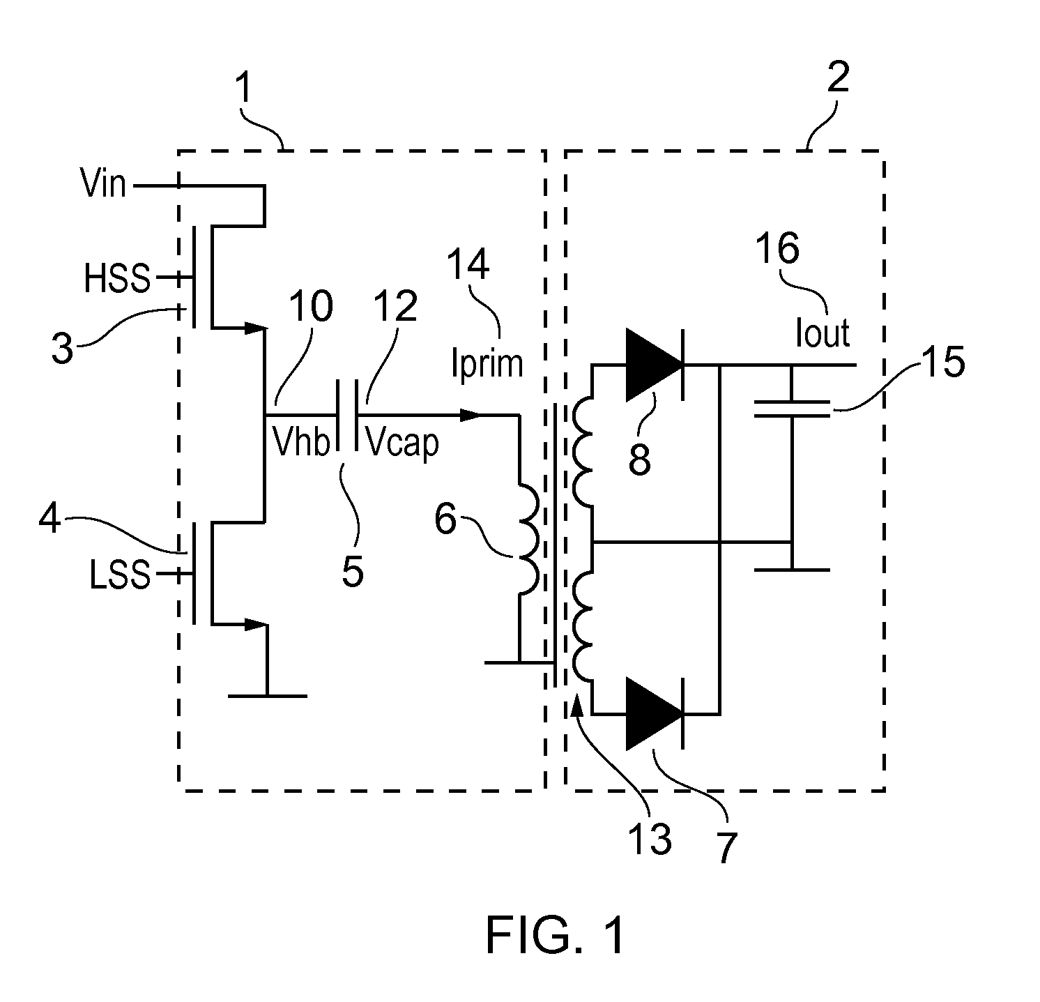
[0037]FIG. 1 shows a resonant power supply for use in accordance with embodiments of the invention. The resonant power supply comprises a primary side circuit 1, and a secondary ...


PUM


Abstract

A method of operating a resonant power converter(1, 2), having a high side switch(3) and a low side switch(4), is disclosed in which the switching is controlled to allow for improved operation at low power levels. The method involved an interruption to the part of the switching cycle in which the low side switch (4) is normally closed, by opening the switch at a particular moment in the cycle which allows the energy to be store in the resonance capacitor (5). Since, as a result, the energy is largely not resonating but stored in a single component, the time quantisation of the mode of operation is significantly reduced or eliminated.

Description

FIELD OF THE INVENTION[0001]The present invention relates to power supplies and in particular to resonant mode power converters.[0002]The present invention is particularly relevant to devices that require a variable level of power, and to devices that require a normal level of power as well as a lower level of power for use in a standby mode. Examples of such devices are consumer electronics such as computers, televisions and the like.BACKGROUND OF THE INVENTION[0003]Power converters for consumer applications typically operate at partial load under standby conditions for a relatively large part of their lifetime. Whilst functioning in this mode, it is desirable to draw power from the mains supply at as low level as is conveniently possible. Therefore it is desirable to use a power converter design for the power supply which operates with a high efficiency not only under full load conditions, but also for partial load, and particularly for low power standby mode.[0004]Power supplies ...

Claims


Application Information

Patent Timeline
IPC IPC(8): H02M3/337
CPCH02M3/3376Y02B70/16Y02B70/1433H02M2001/0032Y02B70/10H02M1/0032
Inventor HALBERSTADT, HANS
Owner NXP BV
Why Eureka
Try Eureka