
Method for inspecting measurement object

a measurement object and inspection method technology, applied in the field of inspection methods of measurement objects, can solve the problems of difficult discrimination of measurement objects, difficult to set up the region of a measurement object from the two-dimensional image, and difficult to discriminate measurement objects, so as to minimize the noise of the shadow region, and enhance the inspection reliability of the measurement object

Active Publication Date: 2011-01-06
KOHYOUNG TECH
View PDF0 Cites 41 Cited by
  • Summary
  • Abstract
  • Description
  • Claims
  • Application Information

AI Technical Summary

Benefits of technology

The patent text describes a method to improve the inspection of a measurement object by minimizing the noise in the shadow regions of a visibility map. This is achieved by compensating the shadow regions using the amplitude information of the directions. Additionally, by extracting the shadow regions using the amplitude maps of the directions with less noise, the reliability of the shadow region may be enhanced.

Problems solved by technology

The technical problem addressed in this patent text is the difficulty in accurately setting up a region of a measurement object on a printed circuit board with electronic devices mounted thereon using a two dimensional image. This is due to the sensitivity of the device to color and illuminators, as well as the potential for noise in the image. A new method is needed to overcome these limitations and inspect the three-dimensional shape of the measurement object.

Method used


Image

  • Method for inspecting measurement object
  • Method for inspecting measurement object
  • Method for inspecting measurement object

Examples


Embodiment Construction

[0061]The invention is described more fully hereinafter with reference to the accompanying drawings, in which embodiments of the invention are shown. This invention may, however, be embodied in many different forms and should not be construed as limited to the embodiments set forth herein. Rather, these embodiments are provided so that this disclosure is thorough, and will fully convey the scope of the invention to those skilled in the art. In the drawings, the size and relative sizes of layers and regions may be exaggerated for clarity. Like reference numerals in the drawings denote like elements.

[0062]It will be understood that when an element or layer is referred to as being “on” or “connected to” another element or layer, it can be directly on or directly connected to the other element or layer, or intervening elements or layers may be present. In contrast, when an element is referred to as being “directly on” or “directly connected to” another element or layer, there are no int...


PUM


Abstract

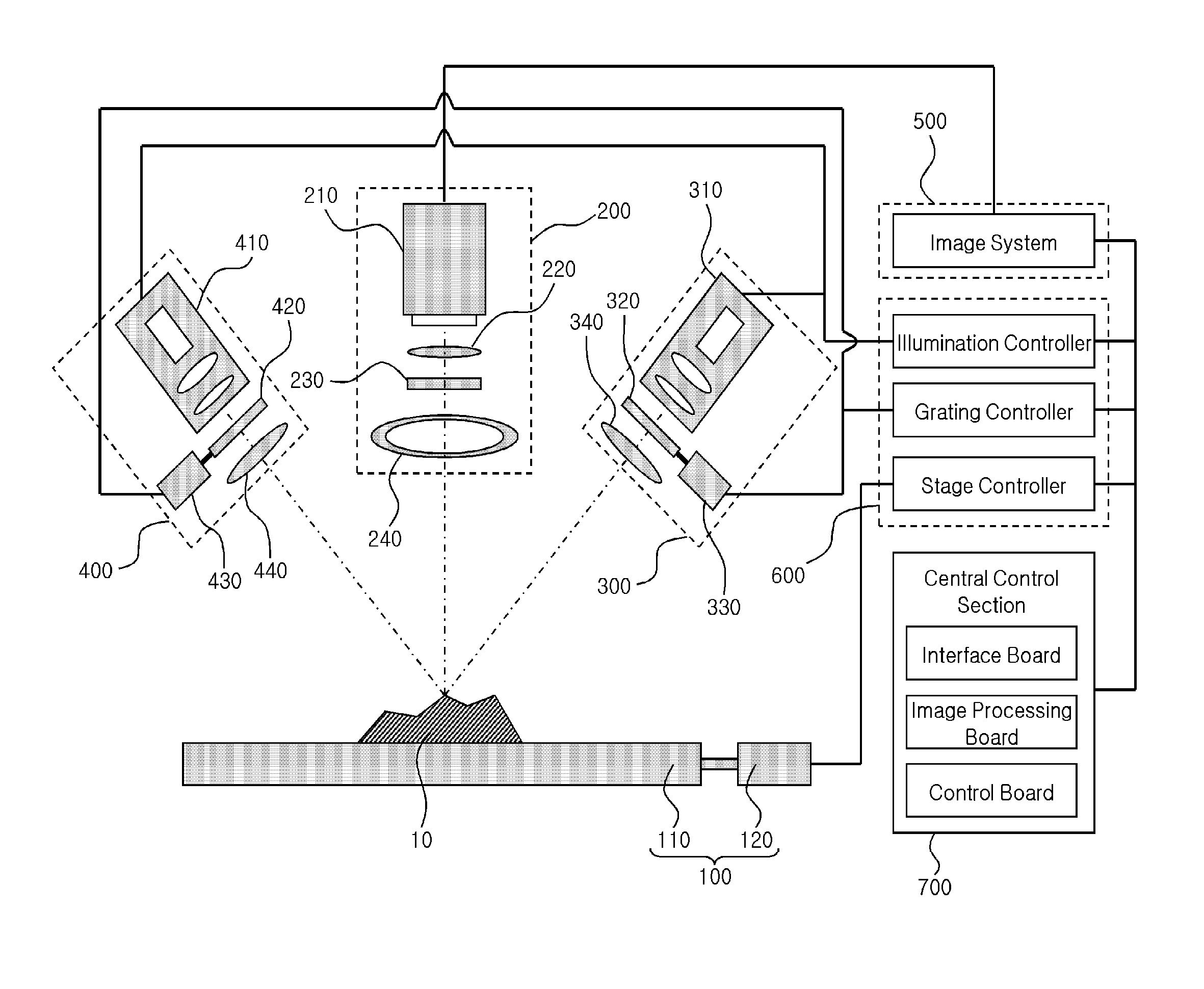
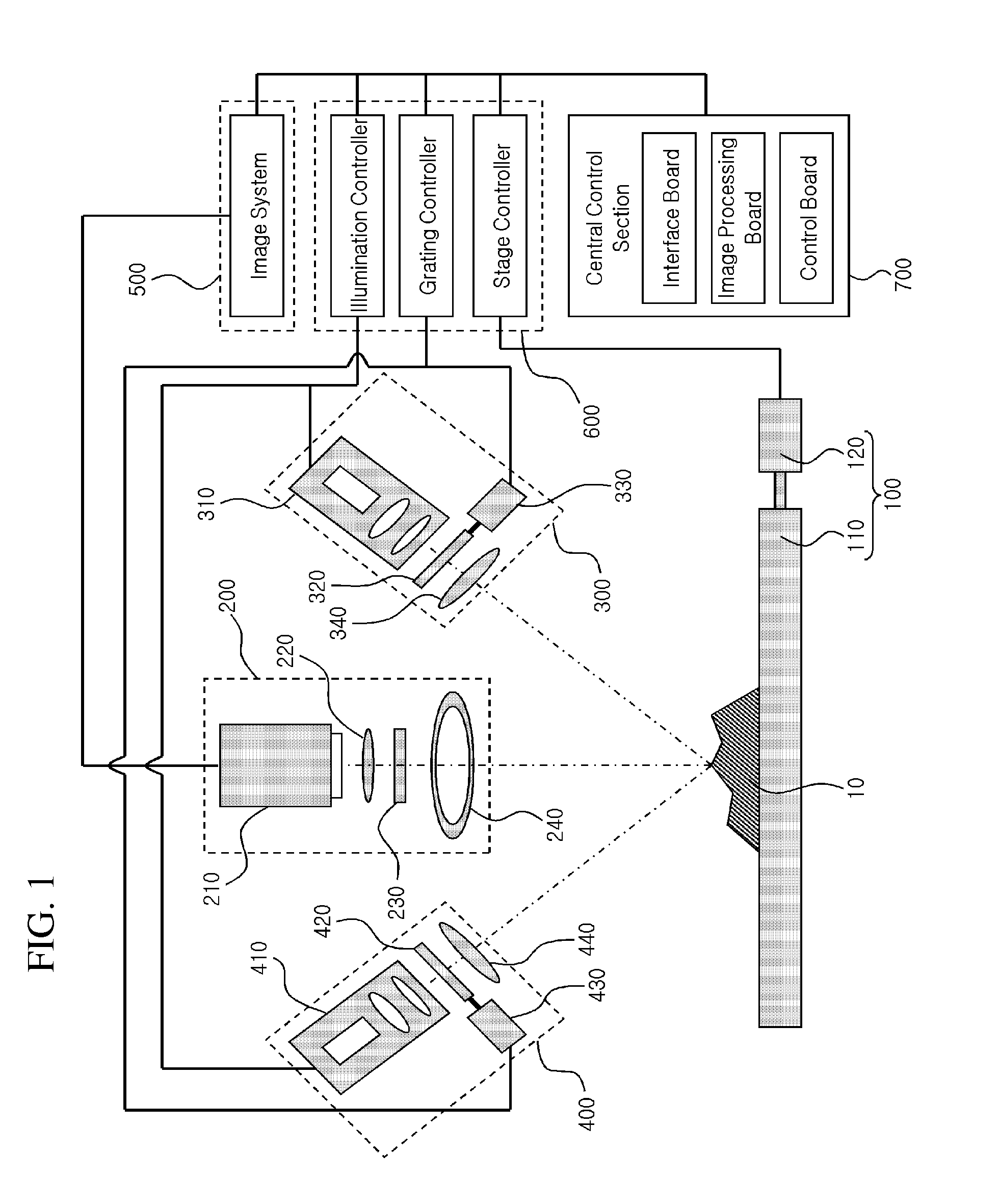
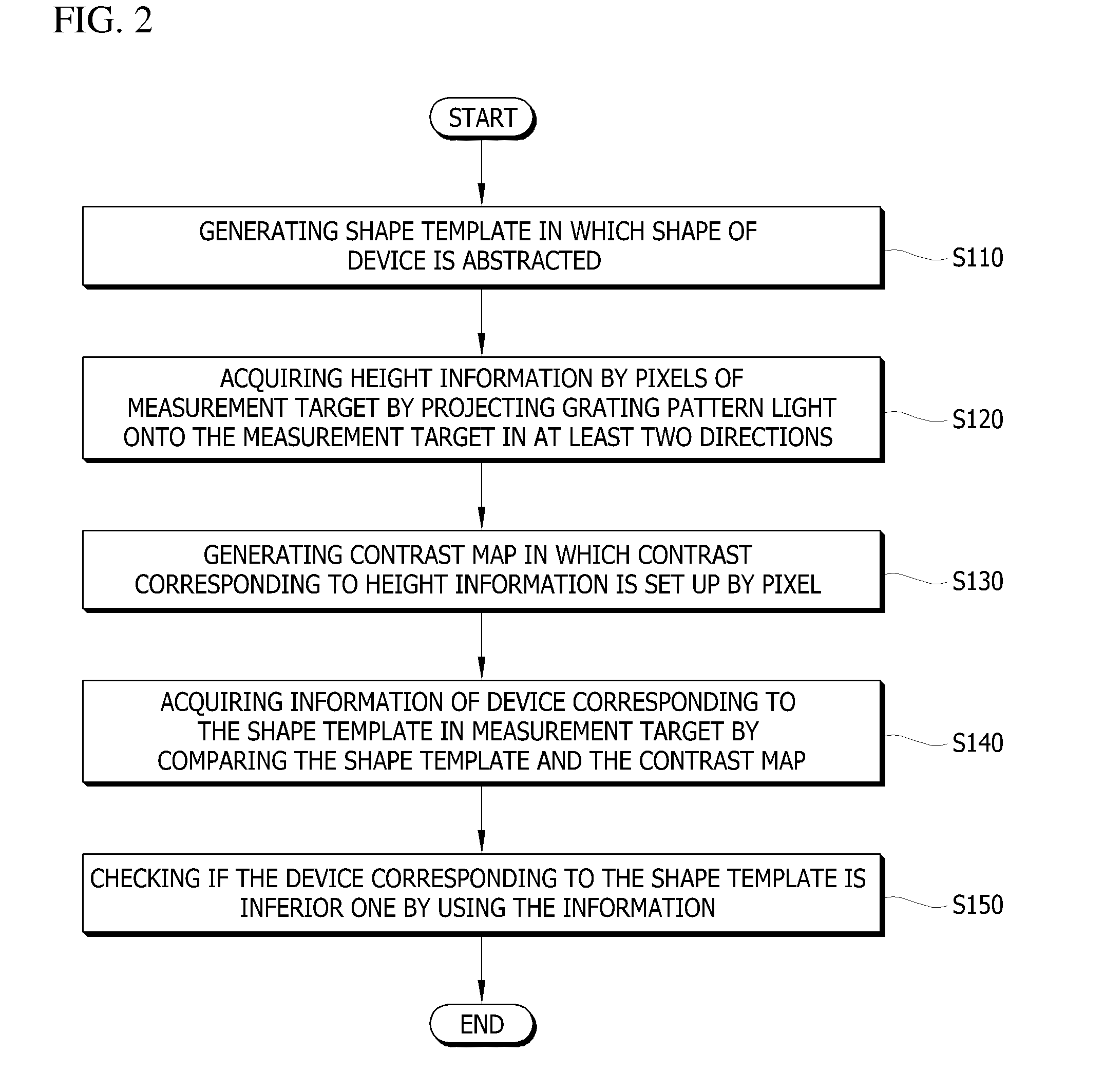
An inspection method for inspecting a device mounted on a substrate, includes generating a shape template of the device, acquiring height information of each pixel by projecting grating pattern light onto the substrate through a projecting section, generating a contrast map corresponding to the height information of each pixel, and comparing the contrast map with the shape template. Thus, a measurement object may be exactly extracted.

Description


Claims


Application Information

Patent Timeline
Owner KOHYOUNG TECH
Learn More