Digital signal discriminator and use method thereof

A digital signal and digital signal output technology, which is applied in the field of signal discriminators, can solve the problems of affecting measurement accuracy, affecting precision, affecting frequency discrimination bandwidth, etc., and achieve the effect of clear process, reasonable structure design, and improved inspection credibility

Inactive Publication Date: 2018-02-23
HUNAN JIAYEDA ELECTRONICS
View PDF9 Cites 4 Cited by
  • Summary
  • Abstract
  • Description
  • Claims
  • Application Information

AI Technical Summary

Problems solved by technology

[0002] With the development of digital technology, many functions that were originally completed by analog circuits are gradually being replaced by digital methods and digital circuits. In recent years, digital intermediate frequency receivers have been developed to enter the stage of practical application. In the machine, a digital frequency discriminator and a numerically controlled oscillator are used to replace the analog frequency discriminator and a voltage-controlled oscillator to form a speed tracking loop in order to obtain higher frequency measurement accuracy. The traditional PD radar seeker uses an analog frequency discriminator and a voltage-controlled oscillator. The controlled oscillator constitutes a speed tracking loop. The frequency discriminator is one of the key components. Its performance index affects the measurement accuracy of the target Doppler frequency, and ultimately affects the accuracy of the terminal guidance correction proportional guidance. The disadvantage of the analog frequency discriminator is that The center frequency and frequency discrimination sensitivity of the frequency discriminator drift with temperature changes, the linearity of the frequency discrimination characteristic curve is poor, and it can only maintain a good linear frequency discrimination slope near the center frequency, thus affecting the frequency discrimination bandwidth

Method used


Image

  • Digital signal discriminator and use method thereof
  • Digital signal discriminator and use method thereof
  • Digital signal discriminator and use method thereof

Examples


Embodiment Construction

[0036] The following will clearly and completely describe the technical solutions in the embodiments of the present invention with reference to the accompanying drawings in the embodiments of the present invention. Obviously, the described embodiments are only some, not all, embodiments of the present invention.

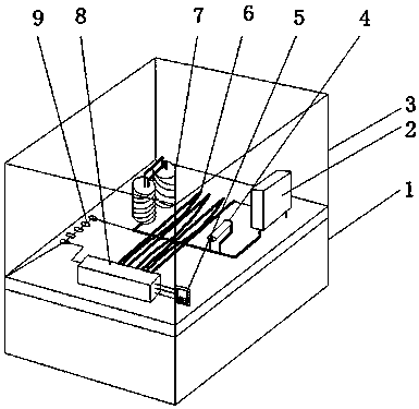
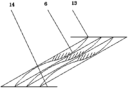
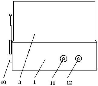
[0037] Examples, see Figure 1-4 , a digital signal discriminator, comprising a base 1, a cover 3 is clamped on the top outer wall of the base 1, and a circuit board is clamped on the top inner wall of the base 1, a through hole is opened on the outer wall of one side of the base 1, and the inner wall of the through hole is clamped There is a digital signal output terminal 12 and a digital signal loading terminal 11, and the digital signal output terminal 12 and the digital signal loading terminal 11 are respectively connected to the output terminal and the input terminal of the circuit board, and a digital low-pass filter is welded on the outer wall of the top of the...


PUM


Abstract

The invention discloses a digital signal discriminator and a use method thereof. The device comprises a base. The outer wall of the top of the base is clamped with an outer cover. The inner wall of the top of the base is clamped with a circuit board. The outer wall of one side of the base is provided with an opening. The inner wall of the through hole is clamped with a digital signal output end and a digital signal loading end, wherein the digital signal output end and the digital signal loading end are connected with the output end and the input end of the circuit board respectively. The method comprises the steps that phase information is acquired through digital phase demodulation; digital discrimination is realized through phase differentiation; and an A/D converter directly samples anintermediate frequency analog signal. According to the invention, the structure design is reasonable; the flow is clear; the intermediate frequency analog signal is input, and finally a high frequency analog signal is simulated and output; signal sampling is extracted and output; the overall process is unified; intermediate frequency transits to low frequency and high frequency; the analog signalis converted into a digital signal, which can improve the test reliability; and compared with intermediate frequency and high frequency analog signals, the digital signal simply needs simple identification.

Description

technical field [0001] The invention relates to the technical field of signal frequency discriminators, in particular to a digital signal frequency discriminator and a use method thereof. Background technique [0002] With the development of digital technology, many functions that were originally completed by analog circuits are gradually being replaced by digital methods and digital circuits. In recent years, digital intermediate frequency receivers have been developed to enter the stage of practical application. In the machine, a digital frequency discriminator and a numerically controlled oscillator are used to replace the analog frequency discriminator and a voltage-controlled oscillator to form a speed tracking loop in order to obtain higher frequency measurement accuracy. The traditional PD radar seeker uses an analog frequency discriminator and a voltage-controlled oscillator. The controlled oscillator constitutes a speed tracking loop. The frequency discriminator is ...

Claims


Application Information

Patent Timeline
Patent Type & Authority Applications(China)
IPC IPC(8): G01R23/12G01S7/285
CPCG01R23/12G01S7/285
Inventor 戴承萍
Owner HUNAN JIAYEDA ELECTRONICS
Why Eureka
Try Eureka