Radio Frequency Front End Circuit with Antenna Diversity for Multipath Mitigation

a technology of antenna diversity and front end circuit, which is applied in the field of radio frequency signal circuitry, can solve the problems of data throughput decline, destructive interference and phase shift, and communications link may cease altogether

Active Publication Date: 2011-01-06
SKYWORKS SOLUTIONS INC
View PDF22 Cites 79 Cited by
  • Summary
  • Abstract
  • Description
  • Claims
  • Application Information

AI Technical Summary

Benefits of technology

[0016]In accordance with one embodiment of the present disclosure, a front end circuit for selectively coupling a first antenna and a second antenna to a transmit chain and a receive chain of a radio frequency (RF) transceiver is contemplated. The front end circuit may include a first power amplifier having an input connectible to the transmit chain of the RF transceiver. The first power amplifier may also have an output. The front end circuit may further include a first low noise amplifier having an output connectible to the receive chain of the RF transceiver. The first low noise amplifier may also have an input. There may be a

Problems solved by technology

Errors may be caused in part by increased noise from the surrounding environment, obstacles and so forth.
If there are a substantial number of retry attempts, data throughput is decreased, or the communications link may cease altogether.
Signal reception problems in WLAN and other systems are typically attributable to multi-path propagation phenomena, where a single signal reaches the antenna via two or more different paths because of obstacles between the transmitter and the counterpart receiver.
At the RF signal level, destructive interference and phase shifts may occur.
Specifically, the signals may be of differing phases and when combined at the receiver, may be weakened to the point of being unrecoverable by the receiver,

Method used


Image

  • Radio Frequency Front End Circuit with Antenna Diversity for Multipath Mitigation
  • Radio Frequency Front End Circuit with Antenna Diversity for Multipath Mitigation
  • Radio Frequency Front End Circuit with Antenna Diversity for Multipath Mitigation

Examples


Embodiment Construction

[0027]The detailed description set forth below in connection with the appended drawings is intended as a description of certain embodiments of the present disclosure, and is not intended to represent the only forms that may be developed or utilized. The description sets forth the various functions in connection with the illustrated embodiments, but it is to be understood, however, that the same or equivalent functions may be accomplished by different embodiments that are also intended to be encompassed within the scope of the present disclosure. It is further understood that the use of relational terms such as first and second and the like are used solely to distinguish one entity from another without necessarily requiring or implying any actual such relationship or order between such entities.

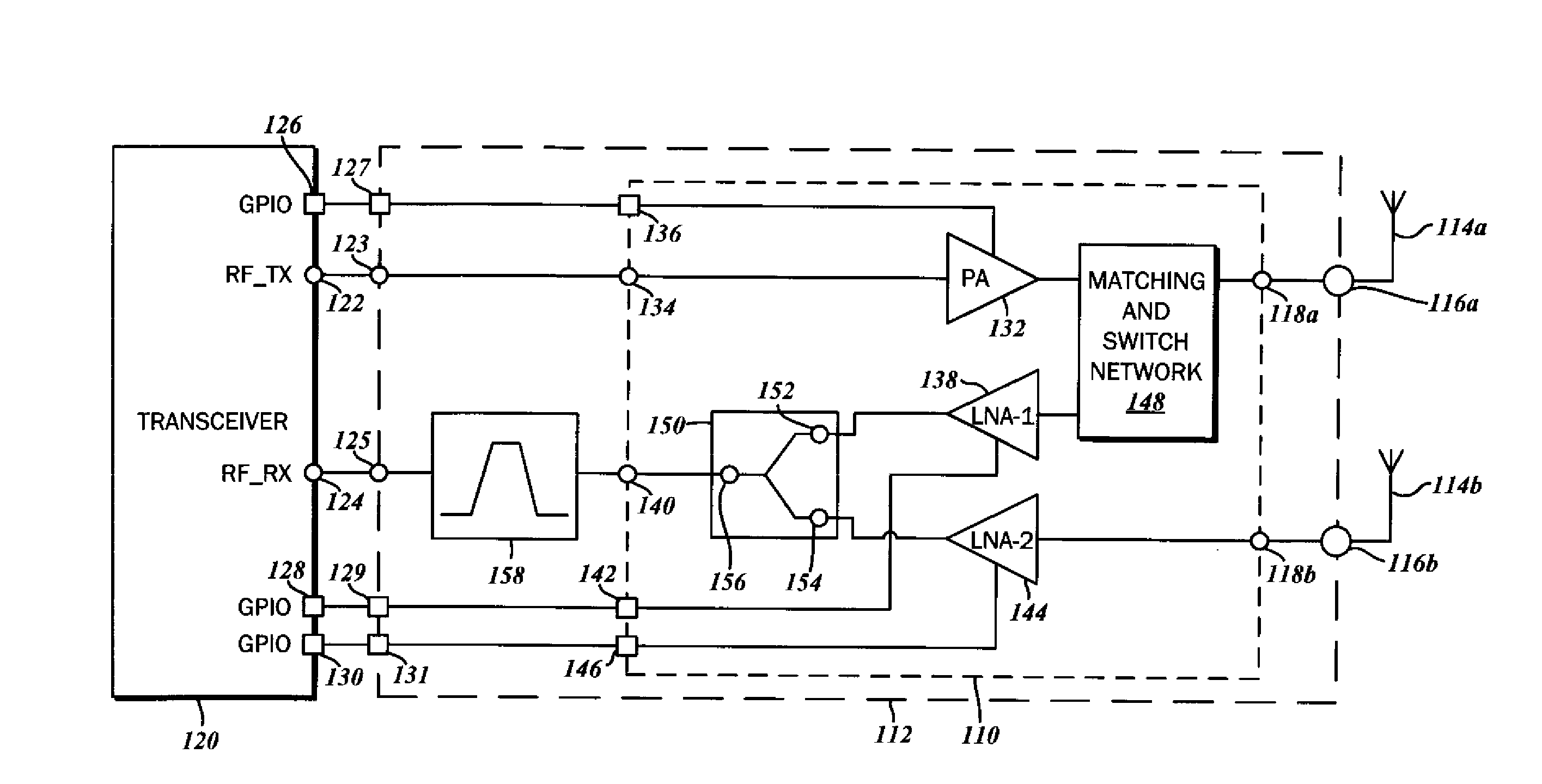
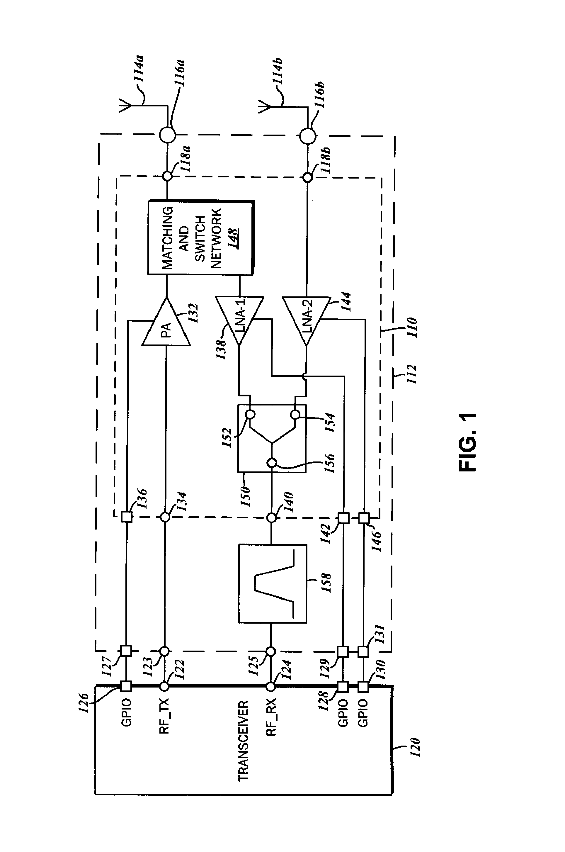
[0028]The block diagram of FIG. 1 illustrates a front end circuit 110 in accordance with one embodiment of the present disclosure. The front end circuit 110 is incorporated into a front end mo...


PUM


Abstract

A front end circuit for selectively coupling a first antenna and a second antenna to a transmit chain and a receive chain of a radio frequency (RF) transceiver is disclosed. There is a first power amplifier having an input connectible to the transmit chain of the RF transceiver, a first low noise amplifier having an output connectible to the receive chain of the RF transceiver, and a second low noise amplifier with an input connectible to the second antenna, as well as an output connectible to the receive chain of the RF transceiver. A first matching and switch network is connected to the first antenna, the output of the first power amplifier, and the input of the first low noise amplifier. Transmit signals from the first power amplifier and receive signals from the first antenna are selectively passed to the first antenna and the first low noise amplifier.

Description

CROSS-REFERENCE TO RELATED APPLICATIONS[0001]This application relates to and claims the benefit of U.S. Provisional Application No. 61 / 223,164, filed Jul. 6, 2009 and entitled “RF FRONT-END TRANSMIT-RECEIVE INTEGRATED CIRCUITS (IC) WITH ANTENNA DIVERSITY,” which is wholly incorporated by reference herein.STATEMENT RE: FEDERALLY SPONSORED RESEARCH / DEVELOPMENT[0002]Not ApplicableBACKGROUND[0003]1. Technical Field[0004]The present invention relates generally to radio frequency (RF) signal circuitry, and more particularly, to RF front end circuits with antenna diversity for multipath mitigation.[0005]2. Related Art[0006]Wireless communications systems find application in numerous contexts involving information transfer over long and short distances alike, and there exists a wide range of modalities suited to meet the particular needs of each. These systems include cellular telephones and two-way radios for distant voice communications, as well as shorter-range data networks for computer...

Claims


Application Information

Patent Timeline
IPC IPC(8): H04B1/44H01P1/10
CPCH01Q21/0025H04B1/44H03H7/463H03H7/38
Inventor GORBACHOV, OLEKSANDR
Owner SKYWORKS SOLUTIONS INC
Why Eureka
Try Eureka