Breast pump for expressing milk from a breast

a breast and pump technology, applied in the field of breast pump for expressing milk, can solve the problems of easy control of settings by users, high manual work of manual driven breast pump, time-consuming operation, etc., and achieve the effect of optimizing breast pump settings, increasing milk quantity, and improving pumping efficiency

Active Publication Date: 2011-01-06
KONINKLIJKE PHILIPS ELECTRONICS NV
View PDF10 Cites 52 Cited by
  • Summary
  • Abstract
  • Description
  • Claims
  • Application Information

AI Technical Summary

Benefits of technology

[0004]To that end, an apparatus according to the invention is characterized in that the breast pump is adapted for optimising breast pump settings by actively controlling at least one breast pump pumping property, based on measurements of the at least one sensor, during a period of use of the breast pump, in order to personalise operation of said breast pump for a particular user. Because the breast pump is able to optimise breast pump settings based on measurements of the at least one sensor during the period of use of the breast pump, thus also before actual milk expression starts and after the milk expression decreases or ends, a breast pump that is adapted to personal characteristics of a particular user is provided. Such a breast pump provides the best settings by actively controlling at least one breast pump pumping property, based on measurements of the at least one sensor for said user during each stage of the actual period of use of the breast pump, in an easy manner witho

Problems solved by technology

Also other reasons, like excessive milk production or breast problems or injuries may result in the woman using a breast pump instead of breast feeding the baby.
For instance, a manually driven breast pump requires a lot of manual work to apply a desired suction frequency and a desired suction power.
This may result in a time consuming operation.
However, in practice it is not easy for a user to control the settings in an intended manner, thereby risking wrong use of the breast pump resultin

Method used


Image

  • Breast pump for expressing milk from a breast
  • Breast pump for expressing milk from a breast

Examples


Embodiment Construction

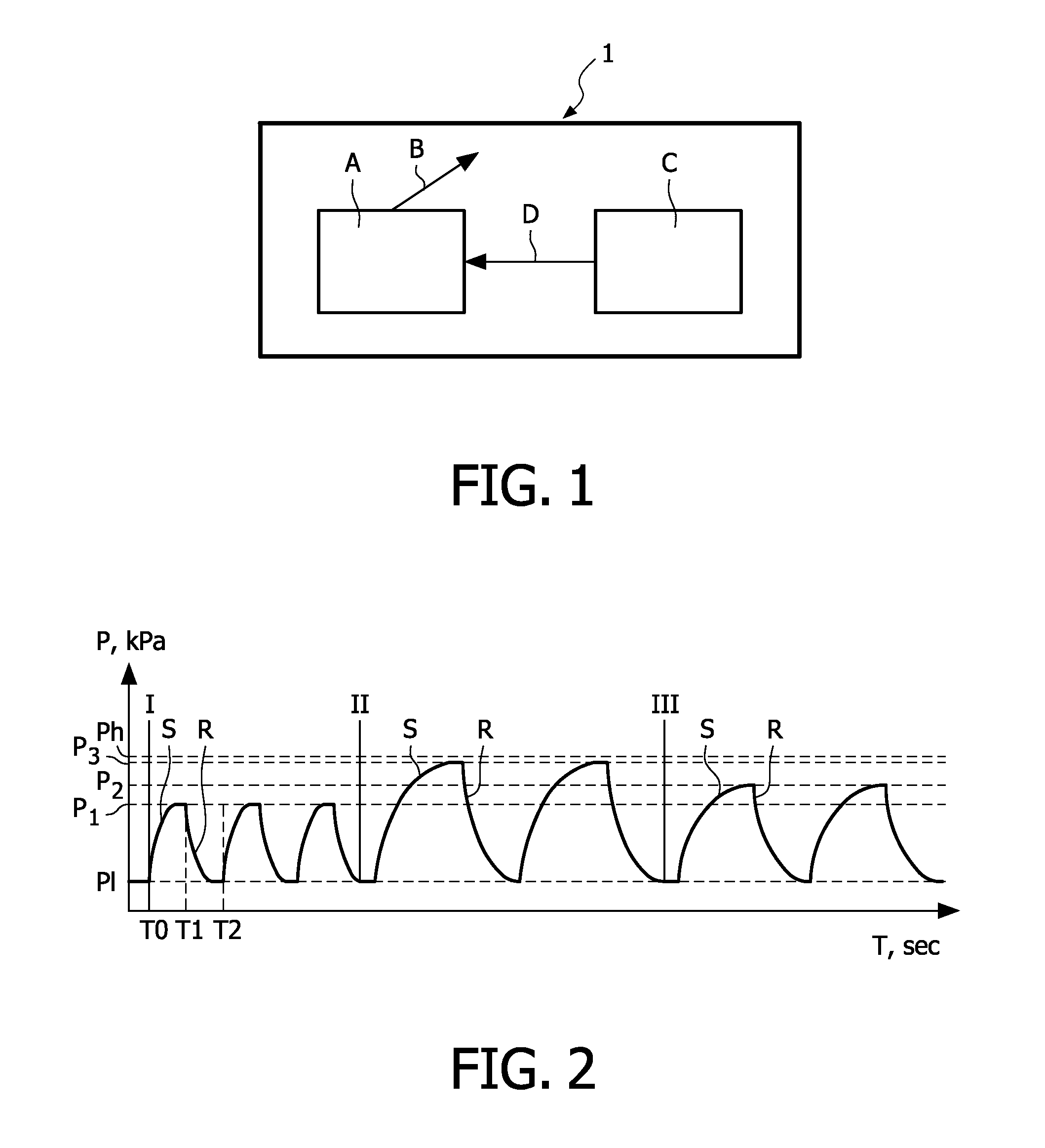
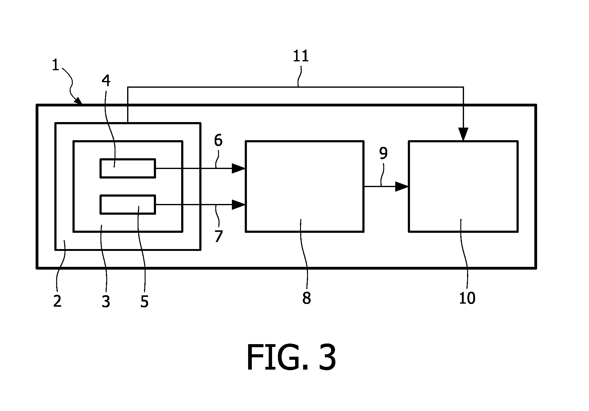
[0020]FIG. 1 shows the working principle of the breast pump 1 according to the invention. Block A represents determining the required settings of the breast pump 1 on a certain moment during the period of use of the breast pump 1, for instance just after starting the breast pump 1. The breast pump 1 is driven to operate with a certain pumping frequency and pumping power, represented by arrow B. Block C represents the measurement of the actual parameters of the entire system, for example maximum negative pressure in the breast shield 2 (see FIG. 3), or at least in the space between the breast shield 2 (see FIG. 3) and the breast, and of the actual milk flow at that moment. After measuring the pressure and the milk flow, the data is transmitted back (represented by arrow D) and is analysed (also represented by block A). According to the analysed data, adapting of the breast pump settings may be suggested, which may be done automatically or manually by the user according to the suggest...


PUM


Abstract

Breast pump for expressing milk from a breast, comprising at least one breast cup (2) for receiving a breast, a pumping system (10) in fluid connection (11) with the at least one breast cup (2) for applying a negative pressure on said breast and a detection unit (3) comprising at least one sensor for measuring a parameter during use of the breast pump (1), wherein the breast pump (1) is adapted for optimising breast pump settings by actively controlling at least one breast pump pumping property, based on measurements of the at least one sensor (4, 5), during a period of use of the breast pump (1), in order to personalise operation of said breast pump (1) for a particular user.

Description

FIELD OF THE INVENTION[0001]The invention relates to a breast pump for expressing milk from a breast, comprising at least one breast cup for receiving a breast, a pumping system in fluid connection with the at least one breast cup for applying a negative pressure on said breast and a detection unit comprising at least one sensor for measuring a parameter during use of the breast pump.BACKGROUND OF THE INVENTION[0002]Breast pumps are devices used for expression of milk from a woman's breast, for instance if the baby is not able to extract the milk itself for different reasons for instance due to suckling problems or when the mother is separated from the baby. Also other reasons, like excessive milk production or breast problems or injuries may result in the woman using a breast pump instead of breast feeding the baby. Different kinds of breast pumps exist, such as manually driven or electrically driven. The known breast pumps have different disadvantages. For instance, a manually dri...

Claims


Application Information

Patent Timeline
IPC IPC(8): A61M1/06
CPCA61M1/0031A61M1/06A61M2205/3344A61M1/0029A61M1/0027A61M1/0025A61M2205/52A61M1/734A61M1/732A61M1/73A61M1/74A61M1/06935
Inventor VAN SCHIJNDEL, NICOLLE HANNEKEKOT, VALERY STEPHANOVICHAARTS, RONALDUS MARIA
Owner KONINKLIJKE PHILIPS ELECTRONICS NV
Why Eureka
Try Eureka