
System and method for energy monitoring and management using a backplane

a backplane and energy monitoring technology, applied in the field of electric systems and machines, can solve the problems of increasing the cost of electricity consumption, increasing the complexity of billing, and increasing the complexity of industrial as well as residential consumers, so as to facilitate high-speed communication, increase speed and performance, and reduce cost

Active Publication Date: 2011-01-06
ROCKWELL AUTOMATION TECH
View PDF18 Cites 30 Cited by
  • Summary
  • Abstract
  • Description
  • Claims
  • Application Information

AI Technical Summary

Benefits of technology

The present invention is a system and method for centrally monitoring and managing loads. It uses sensors to observe load characteristics and a control module to calculate energy data and control power distribution to loads. The invention is faster and more efficient than conventional systems and reduces cost by eliminating multiple power monitors. It can be easily added or removed from automated systems with minimal impact on current operations. The technical effects of the invention include increased speed, improved performance, and reduced cost.

Problems solved by technology

Deregulation has presented businesses with new and complex issues with respect to purchasing and managing energy.
Competition is advantageous for consumers in that they are able to purchase cheaper energy, however competition among generation suppliers produces differing and often-complex pricing schemes.
Today, however, billing is quite a bit more complicated for industrial as well as residential consumers.
Unfortunately, the growth and ubiquity of electrical systems and machines makes energy management a large and increasingly complicated task.
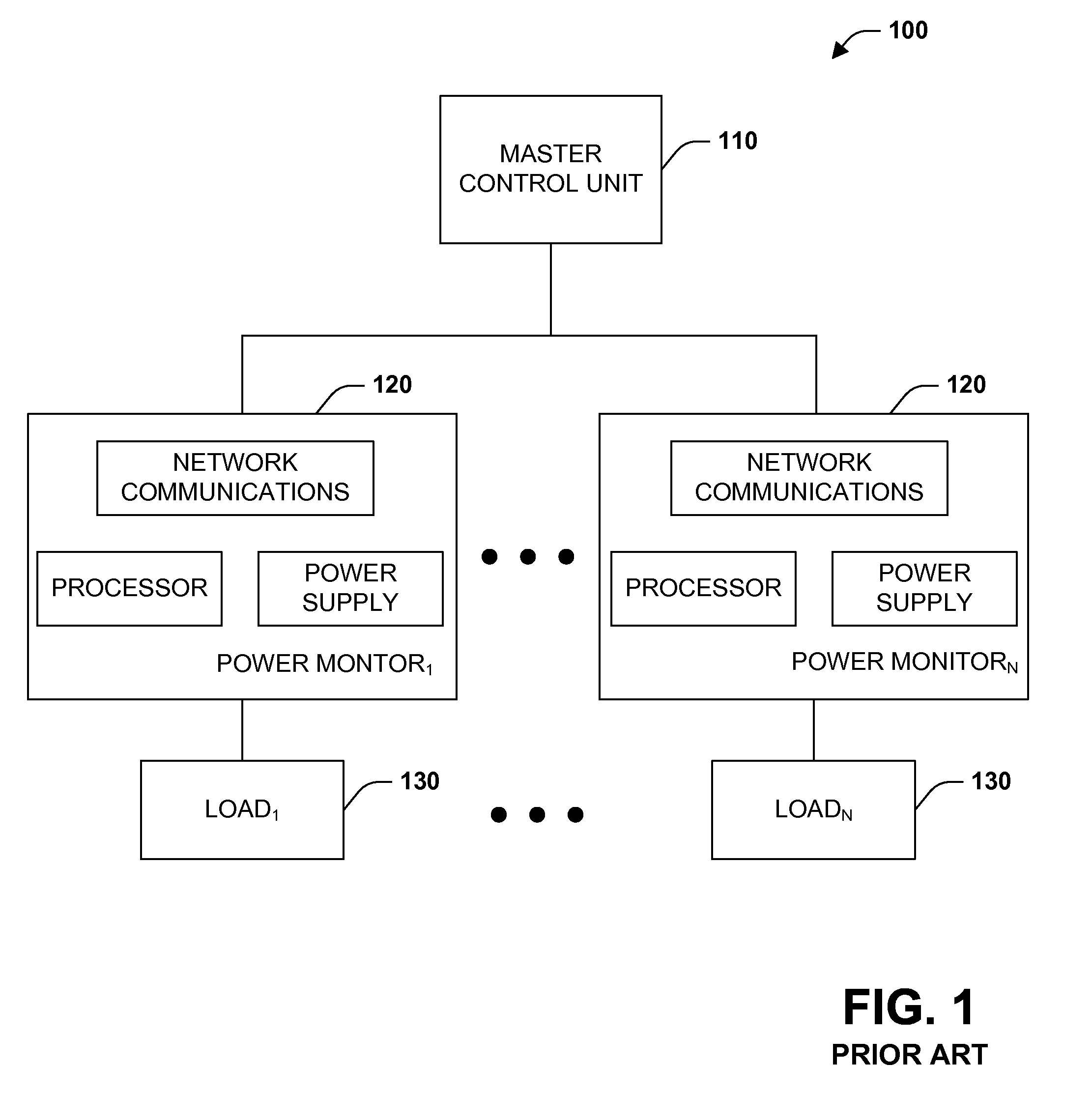
Such an approach is not the best approach at least because it is very expensive to provide a separate power monitor unit for capturing and managing energy data for each load.

Method used


Image

  • System and method for energy monitoring and management using a backplane
  • System and method for energy monitoring and management using a backplane
  • System and method for energy monitoring and management using a backplane

Examples


Embodiment Construction

[0026]The present invention is now described with reference to the annexed drawings, wherein like numerals refer to like elements throughout. It should be understood, however, that the drawings and detailed description thereto are not intended to limit the invention to the particular form disclosed. Rather, the intention is to cover all modifications, equivalents, and alternatives falling within the spirit and scope of the present invention.

[0027]As used in this application, the terms “component” and “system” are intended to refer to a computer-related entity, either hardware, a combination of hardware and software, software, or software in execution. For example, a component may be, but is not limited to being, a process running on a processor, a processor, an object, an executable, a thread of execution, a program, and / or a computer. By way of illustration, both an application running on a server and the server can be a component. One or more components may reside within a process...


PUM


Abstract

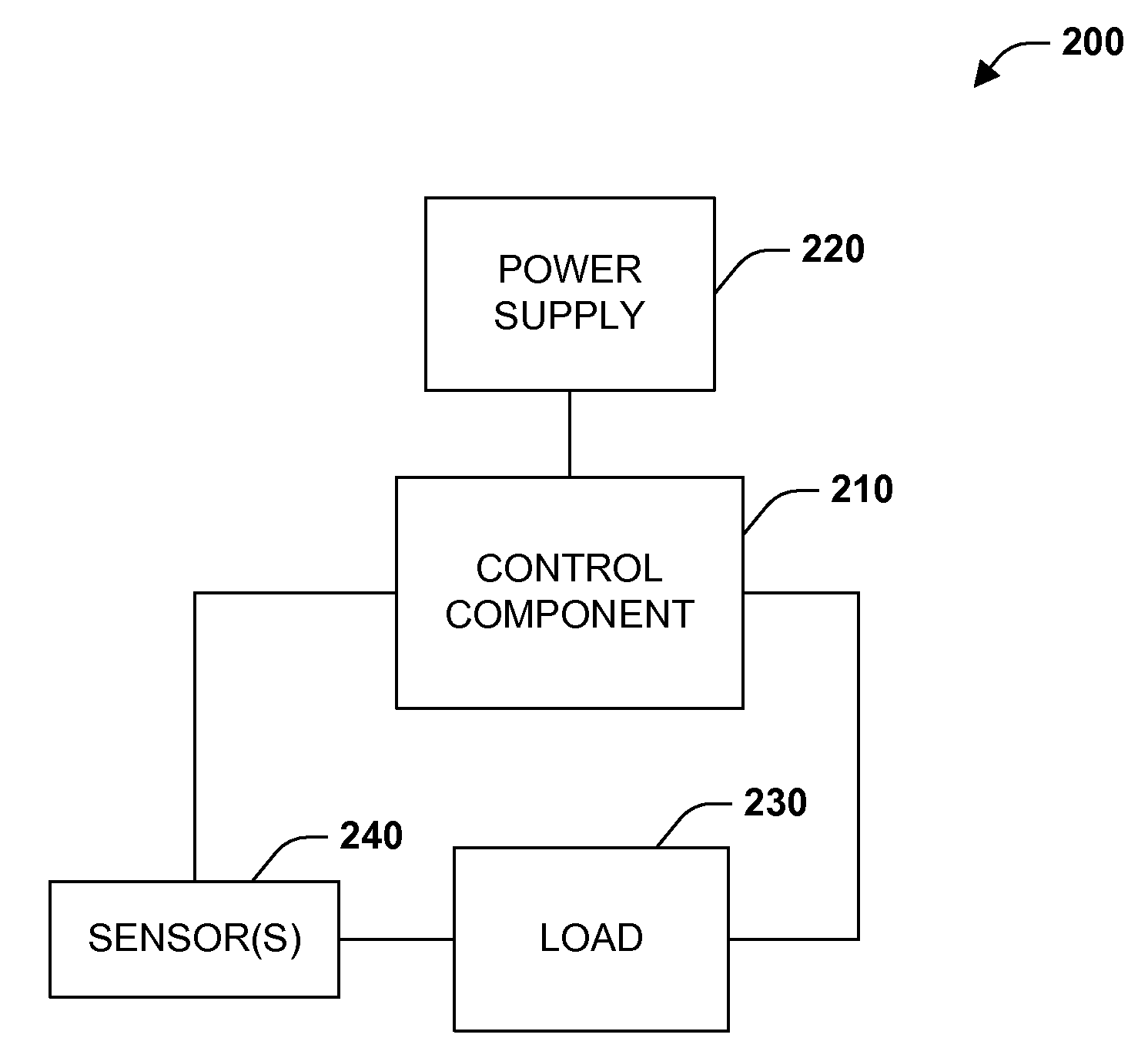
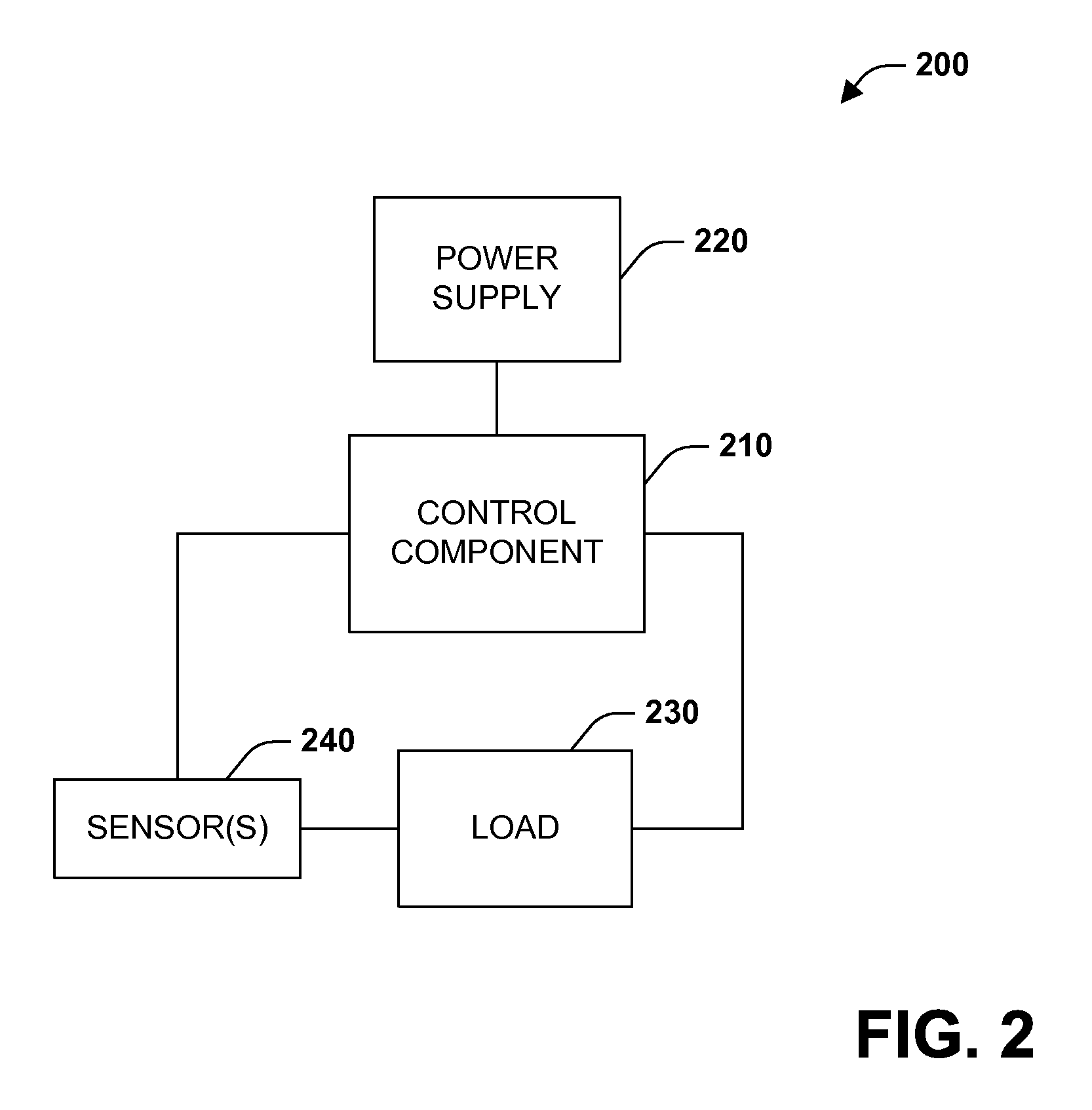
An energy monitoring and management system and method are provided herein. The system and method centralize load metering by utilizing at least one sensor for observing load characteristics (e.g., Volts, Amperes, Watts, active energy . . . ) communicatively coupled via a backplane to a waveform analyzer component of a control component. The waveform analyzer component generates metered data values after receiving input from the at least one sensor. Subsequently and if so desired, the control component can send a control signal to the load to alter the state of the load or simply reduce the power to a load. Such input, output, and processing functionality, according to an aspect of the present invention, are employed using a backplane to facilitate high-speed communication among components and to allow metered data to be centrally stored, manipulated, analyzed or communicated to other components or sub-components.

Description

CROSS-REFERENCE TO RELATED APPLICATIONS[0001]This application is a continuation of U.S. patent application Ser. No. 10 / 673,753, filed Sep. 29, 2003 and entitled SYSTEM AND METHOD FOR ENERGY MONITORING AND MANAGEMENT USING A BACKPLANE, the entirety of which is incorporated herein by reference.TECHNICAL FIELD[0002]The present invention relates generally to electrical systems and machines, and more particularly toward a system and method of monitoring and managing energy utilization.BACKGROUND[0003]Deregulation has presented businesses with new and complex issues with respect to purchasing and managing energy. Utility companies provide a bundle of services including generation, distribution, and transmission. Deregulation has unbundled these services and allowed consumers to chose among a multitude of competing electrical generation suppliers while the local company continues to handle the distribution and transmission of power directly to the consumer. Competition is advantageous for ...

Claims


Application Information

Patent Timeline
Patent Type & Authority Applications(United States)
IPC IPC(8): G01R21/06G06F19/00
CPCG01R19/2513
Inventor WRIGHT, KEVIN P.LOMBARDI, STEVEN A.
Owner ROCKWELL AUTOMATION TECH
Learn More