High strength fin louver design

a technology of louvers and fins, which is applied in the direction of tubular elements, lighting and heating apparatus, and stationary conduit assemblies, etc., can solve the problems of low overall thermal efficiency of heat exchangers, louvered fins, and unlouvered fins, so as to improve the strength of heat exchangers. , the effect of high thermal efficiency

Inactive Publication Date: 2008-06-19
VALEO INC
View PDF11 Cites 4 Cited by
  • Summary
  • Abstract
  • Description
  • Claims
  • Application Information

AI Technical Summary

Benefits of technology

[0011]Various aspects of the present invention propose solutions for prior art problems which improve the strength of the heat exchanger assembly by providing for louvered fins that achieve both high thermal efficiency and high strength simultaneously. By providing for a louvered fin, tube-fin heat exchanger having at least one three-piece single louver, various aspects of the present invention provide for fins with superior characteristics of louvered fin, with reduced areas or zones of boundary layer air, than that of prior art fin designs.
[0012]Various aspects of the present invention, therefore, provide advantages such as increased column strength of louvered fins under compression and design flexibility to put fin strength where it is needed, in spite of the use of louvers with little or no negative impact to the air flow that flows over and around the fin louvers. In addition, these advantages can be obtained at no additional cost of that of louvered fins without the three-piece single louver feature.
[0013]As described herein, the at least one three-piece single louver has a flat area that increases column strength of fins under compression. Looking at the fin height from the fin top to fin bottom, it appears to have a continuous structure in the flat area. In aspects of the present invention, three-piece single louvers with flat areas reduce the total space available for non three-piece louvers. It is therefore clear that location of the three-piece single louver or louvers in the appropriate plane leads to a level of optimization of both fin strength and effectiveness, especially when the flat area of the three-piece single louver is 2 mm or less in width.

Problems solved by technology

Such a boundary layer of air, therefore, results in a low thermal efficiency overall for the heat exchanger due to this boundary layer effect.
But louvered fins, (as opposed to “plain” or “unlouvered” fins), do present drawbacks.
This drawback becomes even more important when the fin gauge is reduced.

Method used


Image

  • High strength fin louver design
  • High strength fin louver design
  • High strength fin louver design

Examples


Embodiment Construction

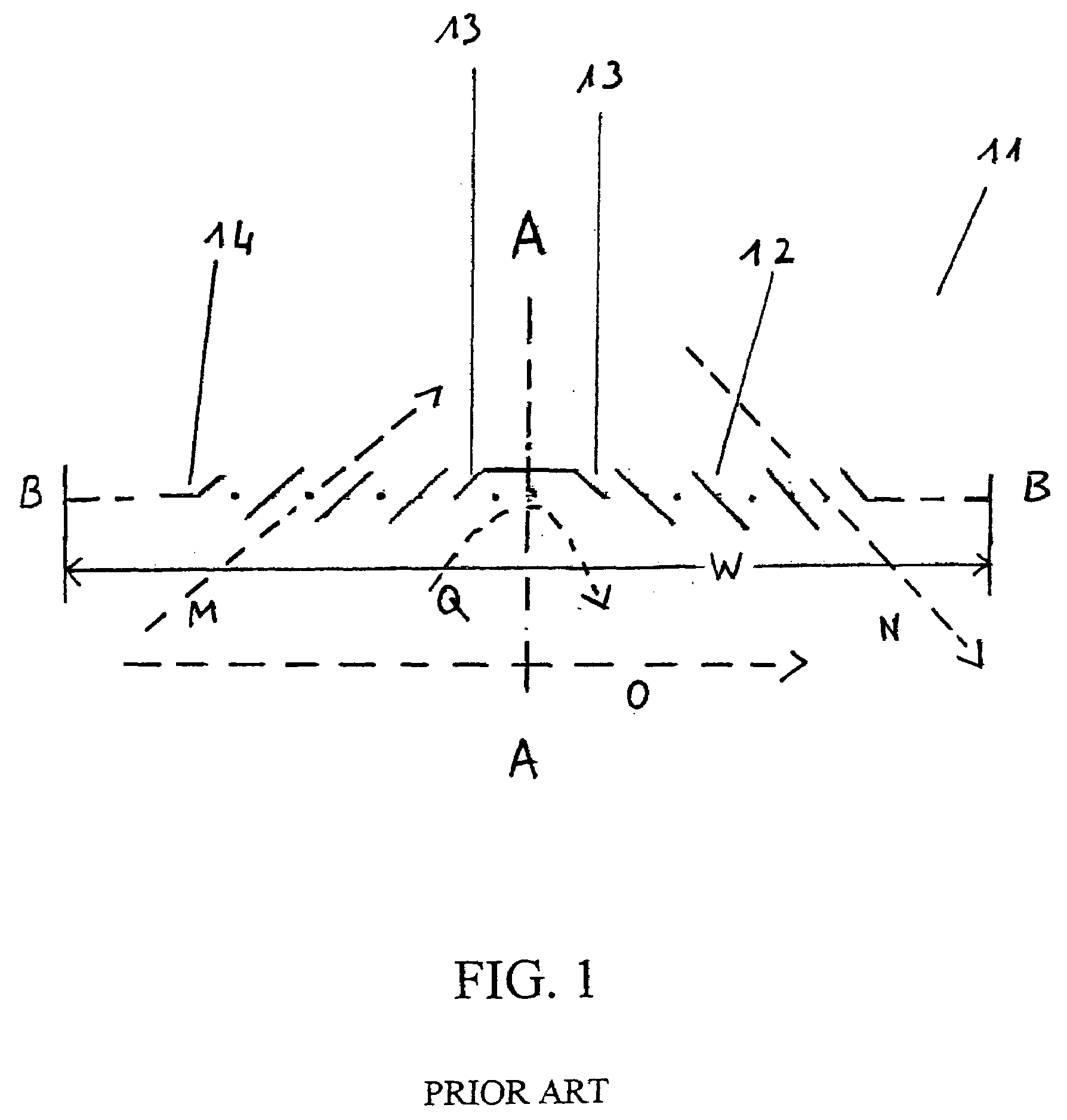
[0035]FIG. 1 illustrates a prior art fin (11) having louvers (12, 14) in a pattern symmetrical around line A - - - A and oriented in a column Axis (A - - - A) represents fin length direction. M represents air flow through one block of non three-piece louver. N represents air flow through another block of non three-piece louver. Q represents air flow at reversal louver. Breaking louver (14), non three-piece louver (12) and reversal louver wings (13) are shown.

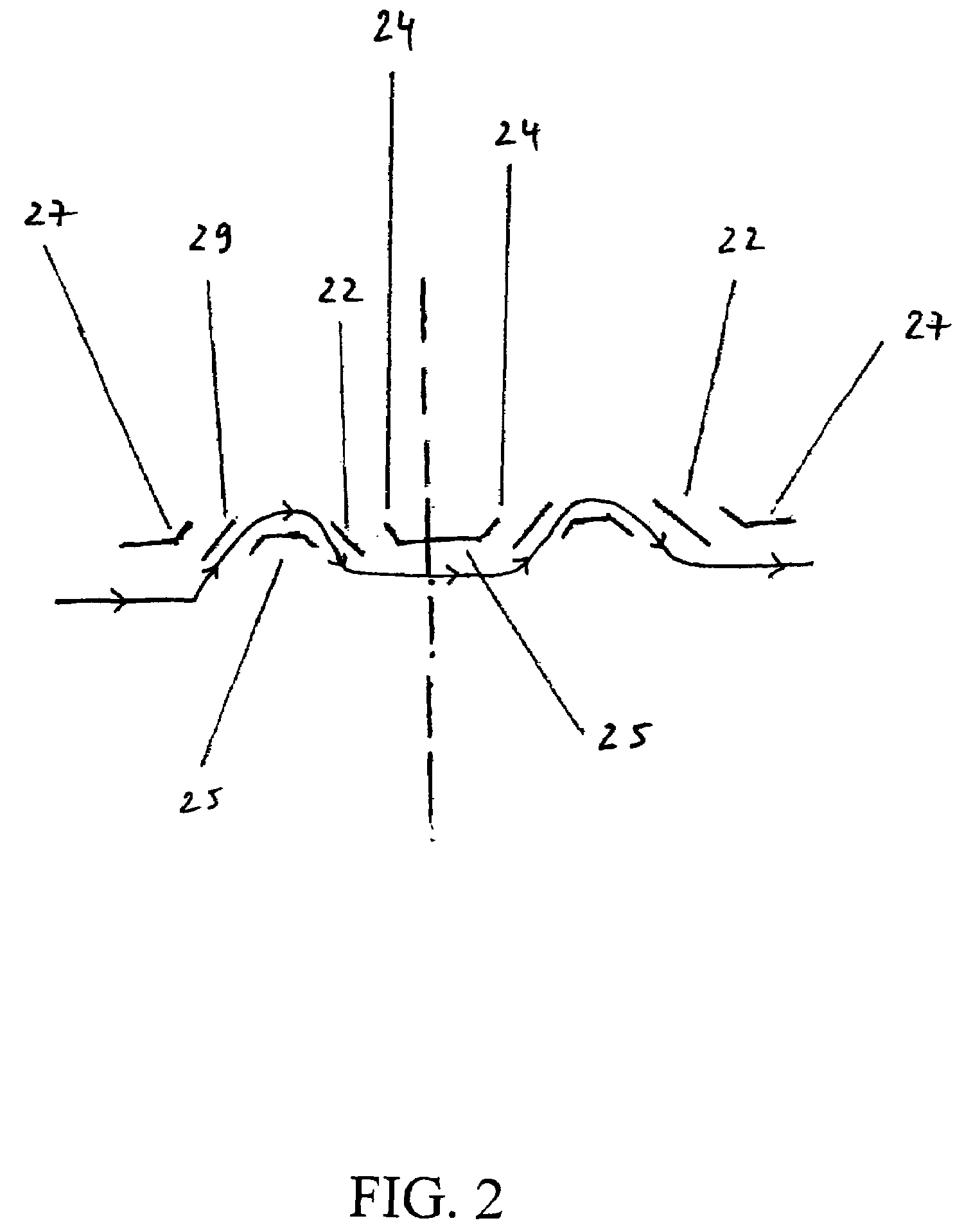
[0036]FIG. 2 shows a fin design in which a non-streamlined inclined three-piece single louver (25) is a reversal louver and has two half louvers (24) and connected by a flat area. In this design, the two downward facing half louvers are along / with similar angles (α), having two opposite directions, therefore forcing air (F) to change flow directions, resulting in additional air side pressure drop.

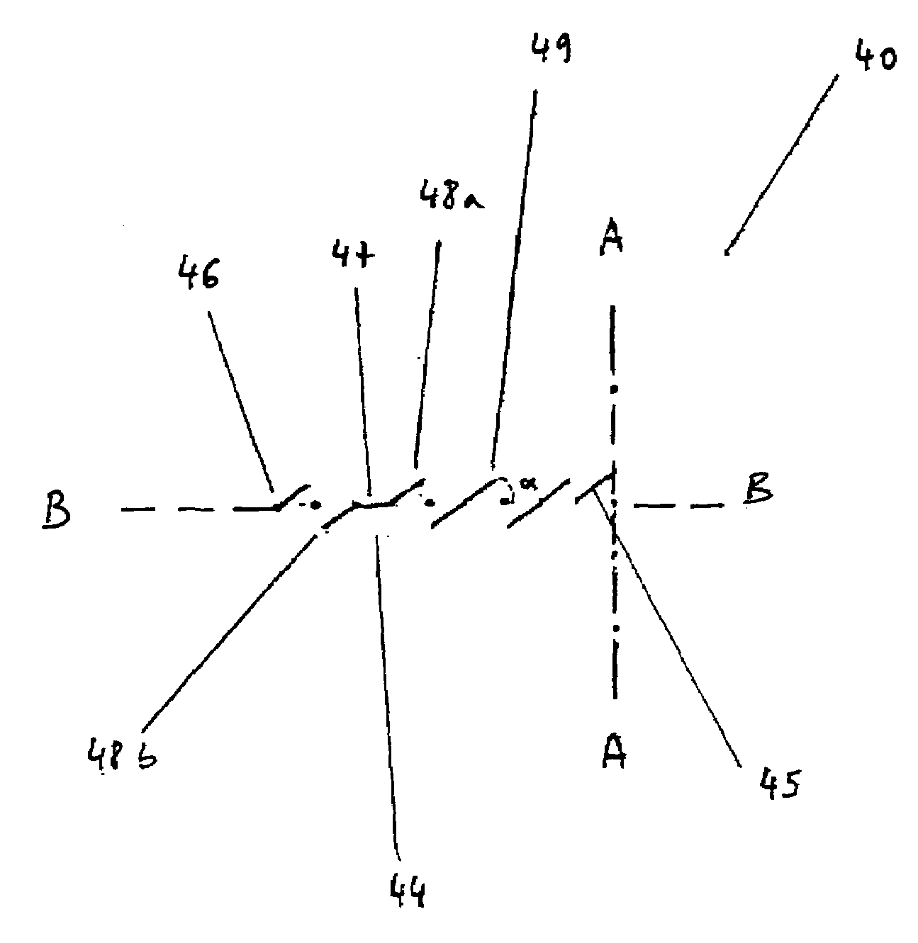
[0037]FIG. 3 illustrates a second louvered fin (31) having louver blocks (32a) (32b) arranged around a central axis (A - - - A), B - -...


PUM


Abstract

Heat exchanger assemblies of increased strength are provided having louvered fins that achieve both high thermal efficiency and high strength simultaneously.
By providing for a three-piece louvered fin, tube-fin heat exchangers having at least one three-piece single louver block, and, in particular, a streamlined inclined three-piece single louver block, exhibit fins with superior characteristics and overall strength for heat exchanger assembly of louvered fin design, with reduced areas or zones of boundary layer air.

Description

FIELD OF THE INVENTION[0001]The present invention relates to heat exchangers having tubes and fins, and, particularly, automotive heat exchangers with fins having louvers.BACKGROUND OF THE INVENTION[0002]Automotive heat exchangers used is applications such as engine cooling, air conditioning and the like, are of various types. Examples of such heat exchangers are the so called plate-fin types and tube-fin types, depending on the conduits and principle heat exchanger areas of the exchangers.[0003]Tube-fin type heat exchangers are the most common. This is due mainly because of their relatively high thermal efficiency, and mass manufacturing friendly design. A tube-fin type heat exchanger, for example, uses a heat carrying liquid (water for radiator, and R134a for condenser, CO2 for gas cooler for example), which can transmit or transfer heat to the tubes, and the tubes, subsequently, can transmit or transfer such heat either by directly (rejecting or otherwise dispersing or dissipatin...

Claims


Application Information

Patent Timeline
Patent Type & Authority Applications(United States)
IPC IPC(8): F28D1/04
CPCF28D1/0391F28F1/128F28D1/05383
Inventor HU, ZAIQIANDOZAL, OMARKENDALL, BRIAN
Owner VALEO INC
Why Eureka
Try Eureka