Methods and systems for removing nitrogen from natural gas

a technology of natural gas liquid and nitrogen recovery, which is applied in the direction of cold treatment separation, liquefaction, lighting and heating apparatus, etc., can solve the problems of capital and operating expenses, lower natural gas recovery, and higher power requirements, so as to reduce capital expenditures and operating expenses, reduce refrigeration horsepower, and reduce the effect of capital expenditures

Inactive Publication Date: 2021-05-27
LINDE ENG NORTH AMERICA
View PDF4 Cites 0 Cited by
  • Summary
  • Abstract
  • Description
  • Claims
  • Application Information

AI Technical Summary

Benefits of technology

[0014]In accordance with the present disclosure, methods and systems are described which reduce or overcome many of the faults of previously known methods and systems. The methods and systems of the present disclosure allow the nitrogen rejection unit to be integrated, i.e., operatively connected, into the natural gas liquids recovery unit with little or no negative impact on the operation of the natural gas liquids recovery unit. The methods and systems of the present disclosure result in reduced refrigeration horsepower in the nitrogen rejection unit versus the sequential natural gas liquids recovery and nitrogen rejection unit processing, resulting in lower capital expenditures and operating expenditures versus sequential natural gas liquids recovery and nitrogen rejection units.

Problems solved by technology

The removal of nitrogen from natural gas can be costly both with respect to CAPEX and OPEX (i.e., capital and operating expenditures).
One of the challenges in such a configuration for an integrated GSP and NRU plant is that normally it is desirable to operate the demethanizer at a pressure lower than the distillation column within the NRU.
As may be seen, current practice may not be adequate for all circumstances, and may result in higher demethanizer pressures, which result in higher power requirements, and / or lower natural gas recovery.
The occurrence of a change in other measured parameters outside the intended ranges may also be alarmed in certain embodiments.

Method used


Image

  • Methods and systems for removing nitrogen from natural gas
  • Methods and systems for removing nitrogen from natural gas
  • Methods and systems for removing nitrogen from natural gas

Examples


embodiment 300

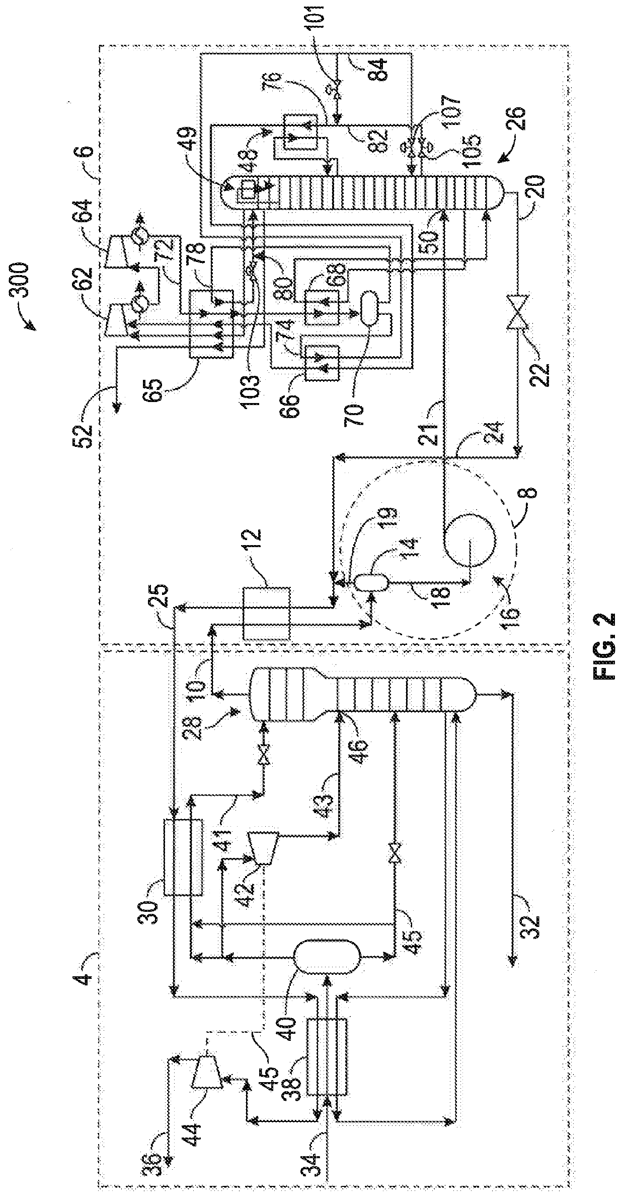
[0067]Process conditions and overall material balance for an example of Embodiment 300 illustrated schematically in FIG. 2 are presented in Tables 2 and 3, however, these conditions and flow rates are to be considered representative and actual conditions and flows may vary depending upon design parameters.

TABLE 2Example Process Conditions - Embodiment 300PressurePressureTemp.Temp.Description(psia)(kPa)(° F.)(C.)NGL Plant Inlet (34)914630212049Cold Separator (40)8996198−15−26Demethanizer Overhead (10)3012075−147−99Demethanizer Bottoms (32)30521036217Residue Product (36)269185515367PMSS Separator (14)2912006−171−113NRU Column Feed (21)3792613−169−112NRU Column Overhead (48)3682537−243−153Nitrogen Reject Stream (52)363250311043NRU Column Bottoms (20)3742579−149−101Flashed NRU Column Bottoms2301586−172−113(24)CH4 Product from NRU (25)2281572−162−108

TABLE 3Example Overall Material Balance - Embodiment 300Mol %Mol %Mol %Mol %TotalN2CH4C2C3+lbmol / hrNGL Plant Feed5.0074.2712.158.5821,959,81...

embodiment 400

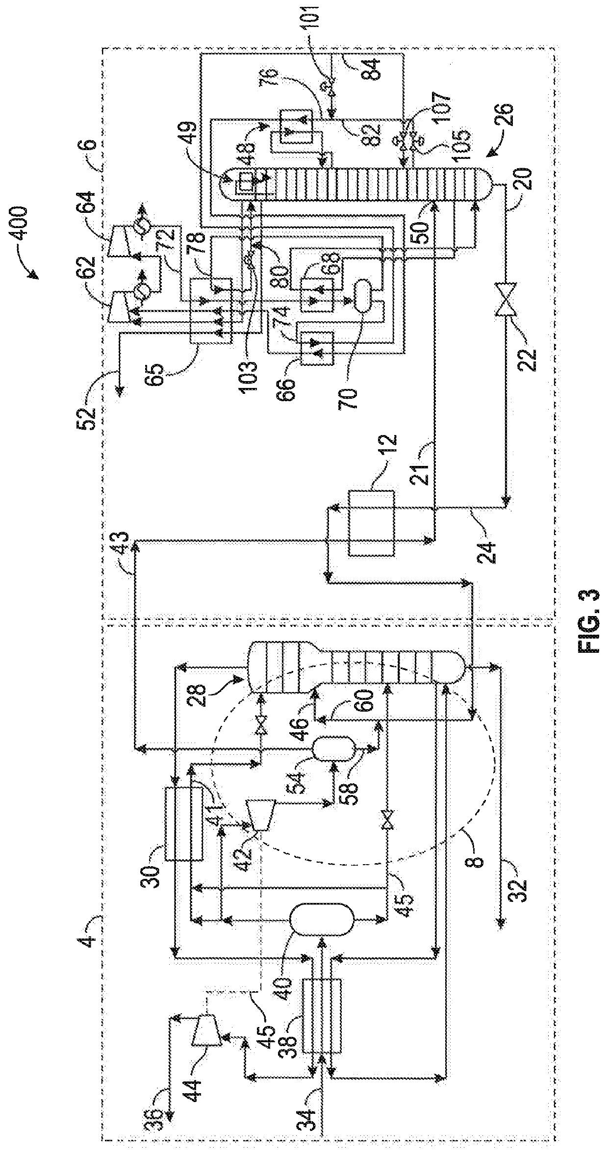
[0070]Process conditions and overall material balance for embodiment 400 illustrated schematically in FIG. 3 are presented in Tables 4 and 5, however, these conditions and flow rates are to be considered representative and actual conditions and flows can vary depending upon design parameters.

TABLE 4Example Process Conditions - Embodiment 400PressurePressureTemp.Temp.Description(psia)(kPa)(° F.)(C.)NGL Plant Inlet (34)914630212049Cold Separator (40)8996198−14−26Demethanizer Overhead (10)2501724−146−99Demethanizer Bottoms (32)2541751478.3Residue Product (36)287197914663Expander Outlet (43)3792613−78−61NRU Column Feed (21)3742579−151−102NRU Column Overhead (49)3682537−243−153Nitrogen Reject Stream (52)363250311043NRU Column Bottoms (20)3742579−146−99Flashed NRU Column Bottoms2591786−163−108(24)Demethanizer Middle Feed (60)2541751−97−72

TABLE 5Example Overall Material Balance - Embodiment 400Mol %Mol %Mol %Mol %TotalN2CH4C2C3+lbmol / hrNGL Plant Feed (34)5.0074.2712.158.5821,959.81NGL Prod...

embodiment 500

[0072]Process conditions and overall material balance for embodiment 500 illustrated schematically in FIG. 4 are presented in Tables 6 and 7, however, these conditions and flow rates are to be considered representative and actual conditions and flows can vary depending upon design parameters.

TABLE 6Example Process Conditions - Embodiment 500PressurePreesureTemp.Temp.Description(psia)(kPa)(° F.)(C.)NGL Plant Inlet (34)914630212049Cold Separator (40)8996198−14−26Demethanizer Overhead2501724−146−99Demethanizer Bottoms (32)2541751478.3Residue Product (36)287197914663Expander Outlet (43)3792613−78−61NRU Column Feed (21)3742579−147−99NRU Column Overhead (49)3682537−243−153Nitrogen Reject Stream (52)363250311043NRU Column Bottoms (20)3742579−142−97Flashed NRU Column Bottoms2591786−160−107(24)Demethanizer Middle Feed (60)2541751−97−72

TABLE 7Example Overall Material Balance - Embodiment 500Mol %Mol %Mol %Mol %TotalN2CH4C2C3+lbmol / hrNGL Plant Feed (34)5.0074.2712.158.5821,959.81NGL Product (3...


PUM


Abstract

Methods and systems for producing a product natural gas employing a natural gas liquids (NGL) recovery unit followed by removing nitrogen in a nitrogen rejection unit (NRU) operatively connected with the NGL recovery unit by a pressure management sub-system (PMSS). In one embodiment, the PMSS includes a first conduit fluidly connecting the top of a demethanizer column (or an existing conduit connected to the top of the demethanizer) to a separator, a second conduit fluidly connecting the separator to a pump, the pump connected to a distillation column in the NRU by a third conduit, in another embodiment, the PMSS includes a first conduit fluidly connecting an NGL expander to a separator, allowing natural gas vapors and nitrogen to be fed to the NRU column through a second conduit. Alternatively, the PMSS allows mixture from the NGL recovery unit expander to be fed directly via the first conduit to the NRU distillation column.

Description

CROSS-REFERENCE TO RELATED APPLICATIONS[0001]This application is entitled to and claims the benefit of earlier filed provisional application Ser. No. 62 / 654,684, filed Apr. 9, 2018, under 35 U.S.C. § 119(e), which earlier filed provisional application is incorporated by reference herein in its entirety.BACKGROUND INFORMATIONTechnical Field[0002]The present disclosure relates to methods and systems for managed pressure natural gas liquids (NGL) and nitrogen recovery in the hydrocarbon production field. In particular, the present disclosure relates to methods and systems featuring any one of a variety of NGL plants and any one of a variety of nitrogen rejection units operatively connected by a managed pressure sub-system so that the NGL plant and the nitrogen rejection plant may each be operated more efficiently, and / or with reduced capital expenditure.Background Art[0003]Natural gas passing through transmission lines (conduits) frequently has an upper limit on the allowable nitrogen ...

Claims


Application Information

Patent Timeline
Patent Type & Authority Applications(United States)
IPC IPC(8): F25J3/02
CPCF25J3/0209F25J3/0257F25J3/0295F25J2200/04F25J2200/40F25J2290/40F25J2200/70F25J2205/04F25J2235/60F25J2240/12F25J2200/50C07C7/09C07C7/005F25J3/0233F25J3/0238F25J2240/02F25J2270/88F25J2205/02F25J2270/902C07C9/04F25J2290/12
Inventor BIGGER, KATHRYN
Owner LINDE ENG NORTH AMERICA
Why Eureka
Try Eureka