System and method for energy monitoring and management using a backplane

a backplane and energy monitoring technology, applied in the field of electric systems and machines, can solve the problems of increasing the cost of electricity consumption, increasing the complexity of billing, and increasing the complexity of industrial as well as residential consumers, so as to facilitate high-speed communication, increase speed and performance, and reduce cost

Active Publication Date: 2007-04-24
ROCKWELL AUTOMATION TECH
View PDF16 Cites 47 Cited by
  • Summary
  • Abstract
  • Description
  • Claims
  • Application Information

AI Technical Summary

Benefits of technology

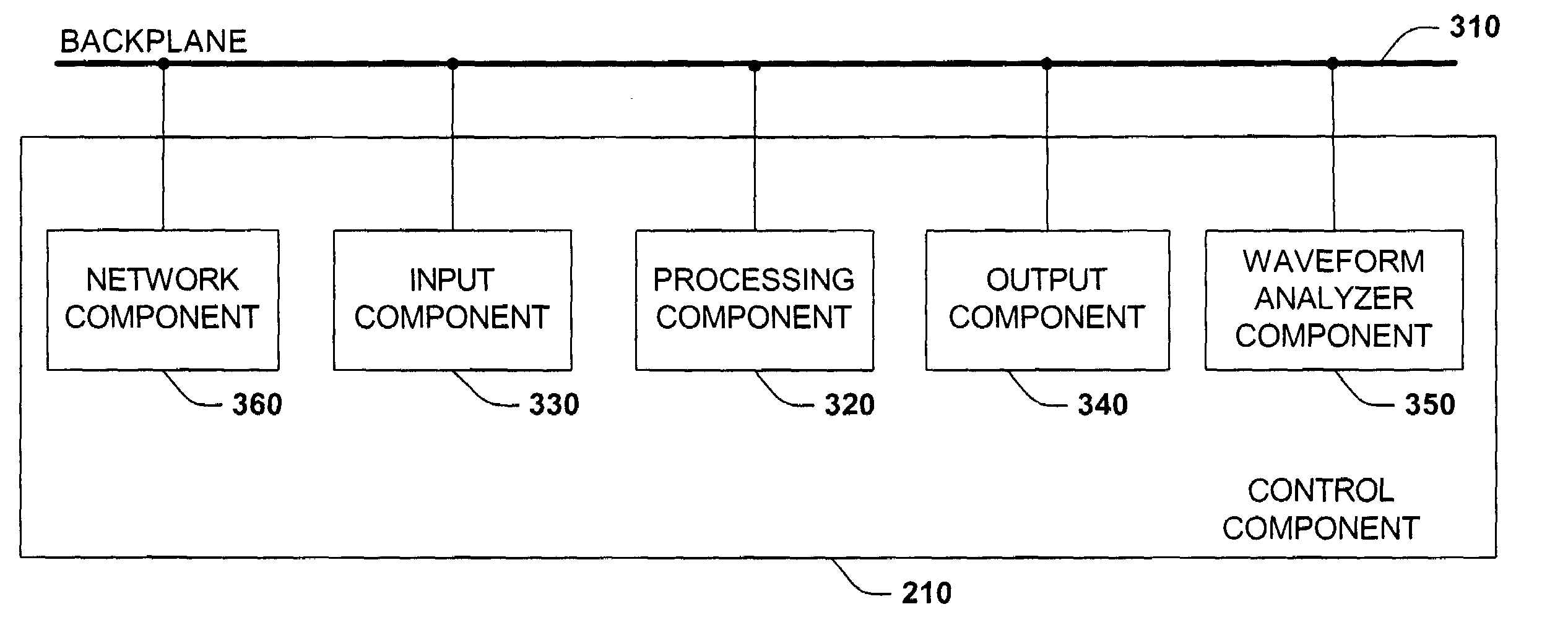
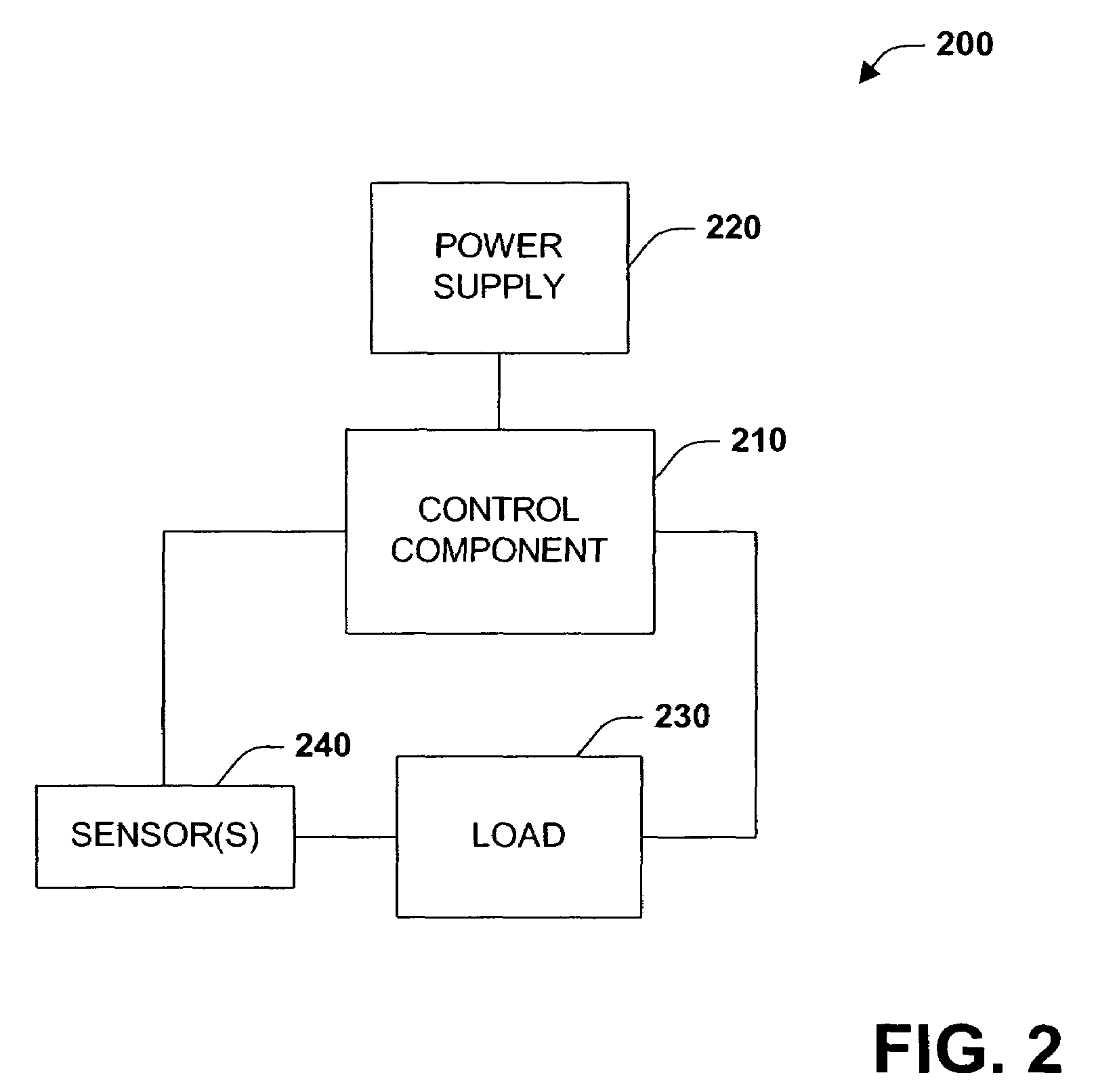
[0006]In accordance with the present invention, a system and method for centrally monitoring and managing loads is disclosed. The system and method centralize load metering by utilizing at least one sensor for observing load characteristics (e.g., Volts, Amperes, Watts, active energy . . . ) communicatively coupled via a backplane to a control module. The control module can contain, inter alia, a waveform analyzer component, which can produce metered energy data values (e.g., total energy consumed, harmonic distortion, power factor) from sensor data. More specifically, the waveform analyzer component captures input data from sensors (e.g., Volts, Amperes, Watts) associated with a load, time stamps the data as it is received, and stores a sequence of events (SOE) in a memory. The waveform analyzer can subsequently use the SOE to calculate energy data. Thereafter and if so desired, the waveform analyzer component, in cooperation with the other control module components (e.g., processing component, input / output modules), can control the power distributed to at least one load based in part on the generated energy data. It should be noted that such input, output, and processing functionality, according to an aspect of the present invention, are employed utilizing a backplane to facilitate high-speed communication among components and to allow metered data to be centrally stored, manipulated, analyzed or communicated to other components or sub-components.
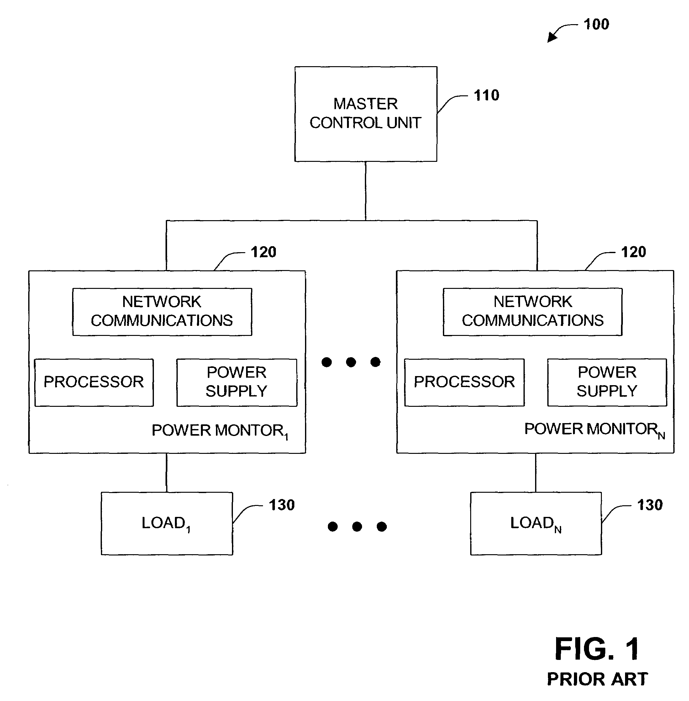
[0007]The subject invention as disclosed herein enjoys many advantages and benefits over conventional systems including but not limited to increased speed and performance as well as reduced cost. The present invention is much faster than conventional systems. By limiting the sensed data to only a few basic parameters (e.g., Volts, Amperes, Watts) and tying the sensed data directly to a backplane, the speed at which data can be processed by a processor component is drastically increased. One reason for the increased speed is the processing power available to a backplane device is much higher than for a remotely located power monitor unit. Furthermore, the subject invention reduces cost by eliminating a multitude of independent and self-contained power monitors in favor of a centralized load control system performed utilizing a backplane. Additionally, by monitoring energy utilizing a backplane in a PLC (Programmable Logic Controller) or SLC (Small Logic Controller), for example, such data can be easily accessed and employed as a decision parameter in automated systems. Still further yet, implementing metering functionality on a removable circuit board (e.g., PLC / SLC card or module) enables such metering functionality to be added and / or removed from an automated system with little or no negative impact on the current operations.

Problems solved by technology

Deregulation has presented businesses with new and complex issues with respect to purchasing and managing energy.
Competition is advantageous for consumers in that they are able to purchase cheaper energy, however competition among generation suppliers produces differing and often-complex pricing schemes.
Today, however, billing is quite a bit more complicated for industrial as well as residential consumers.
Unfortunately, the growth and ubiquity of electrical systems and machines makes energy management a large and increasingly complicated task.
Such an approach is not the best approach at least because it is very expensive to provide a separate power monitor unit for capturing and managing energy data for each load.

Method used


Image

  • System and method for energy monitoring and management using a backplane
  • System and method for energy monitoring and management using a backplane
  • System and method for energy monitoring and management using a backplane

Examples


Embodiment Construction

[0025]The present invention is now described with reference to the annexed drawings, wherein like numerals refer to like elements throughout. It should be understood, however, that the drawings and detailed description thereto are not intended to limit the invention to the particular form disclosed. Rather, the intention is to cover all modifications, equivalents, and alternatives falling within the spirit and scope of the present invention.

[0026]As used in this application, the terms “component” and “system” are intended to refer to a computer-related entity, either hardware, a combination of hardware and software, software, or software in execution. For example, a component may be, but is not limited to being, a process running on a processor, a processor, an object, an executable, a thread of execution, a program, and / or a computer. By way of illustration, both an application running on a server and the server can be a component. One or more components may reside within a process...


PUM


Abstract

An energy monitoring and management system and method are provided herein. The system and method centralize load metering by utilizing at least one sensor for observing load characteristics (e.g., Volts, Amperes, Watts, active energy . . . ) communicatively coupled via a backplane to a waveform analyzer component of a control component. The waveform analyzer component generates metered data values after receiving input from the at least one sensor. Subsequently and if so desired, the control component can send a control signal to the load to alter the state of the load or simply reduce the power to a load. Such input, output, and processing functionality, according to an aspect of the present invention, are employed using a backplane to facilitate high-speed communication among components and to allow metered data to be centrally stored, manipulated, analyzed or communicated to other components or sub-components.

Description

TECHNICAL FIELD[0001]The present invention relates generally to electrical systems and machines, and more particularly toward a system and method of monitoring and managing energy utilization.BACKGROUND[0002]Deregulation has presented businesses with new and complex issues with respect to purchasing and managing energy. Utility companies provide a bundle of services including generation, distribution, and transmission. Deregulation has unbundled these services and allowed consumers to chose among a multitude of competing electrical generation suppliers while the local company continues to handle the distribution and transmission of power directly to the consumer. Competition is advantageous for consumers in that they are able to purchase cheaper energy, however competition among generation suppliers produces differing and often-complex pricing schemes. Although time varying billing rates existed for industrial consumers prior to deregulation, the billing was quite straightforward. I...

Claims


Application Information

Patent Timeline
Patent Type & Authority Patents(United States)
IPC IPC(8): G01R21/00
CPCG01R19/2513
Inventor WRIGHT, KEVIN P.LOMBARDI, STEVEN A.
Owner ROCKWELL AUTOMATION TECH
Why Eureka
Try Eureka