Solenoid valve assembly

a technology of solenoid valves and valve housings, which is applied in the direction of valve housings, valve operating means/release devices, servomotors, etc., can solve the problem of requiring comparatively high air volumes to actuate the piston

Active Publication Date: 2011-01-13
VANDERBILT UNIV
View PDF9 Cites 14 Cited by
  • Summary
  • Abstract
  • Description
  • Claims
  • Application Information

AI Technical Summary

Benefits of technology

[0015]Certain embodiments comprise a housing having: an outer surface; an inner surface forming an internal bore; a first end; a second end; a supply port; an exhaust port; a first outlet port; and a second outlet port, wherein the supply port, the exhaust port, the first outlet port and the second outlet port each extend from the outer surface of the housing to the inner surface of the housing. Certain embodiments also comprise a sliding member received within the internal bore, wherein the sliding member comprises a plurality of sealing members configured to prevent fluid communication between a pair of adjacent ports; and a plurality of recesses configured to allow fluid communication between a pair of adjacent ports, wherein a first recess allows communication between the first outlet port and the second outlet port when the sliding member is positioned at an intermediate position between the first end and the second end.

Problems solved by technology

Such designs therefore require comparatively high volumes of air to actuate the piston.

Method used


Image

  • Solenoid valve assembly
  • Solenoid valve assembly
  • Solenoid valve assembly

Examples


Embodiment Construction

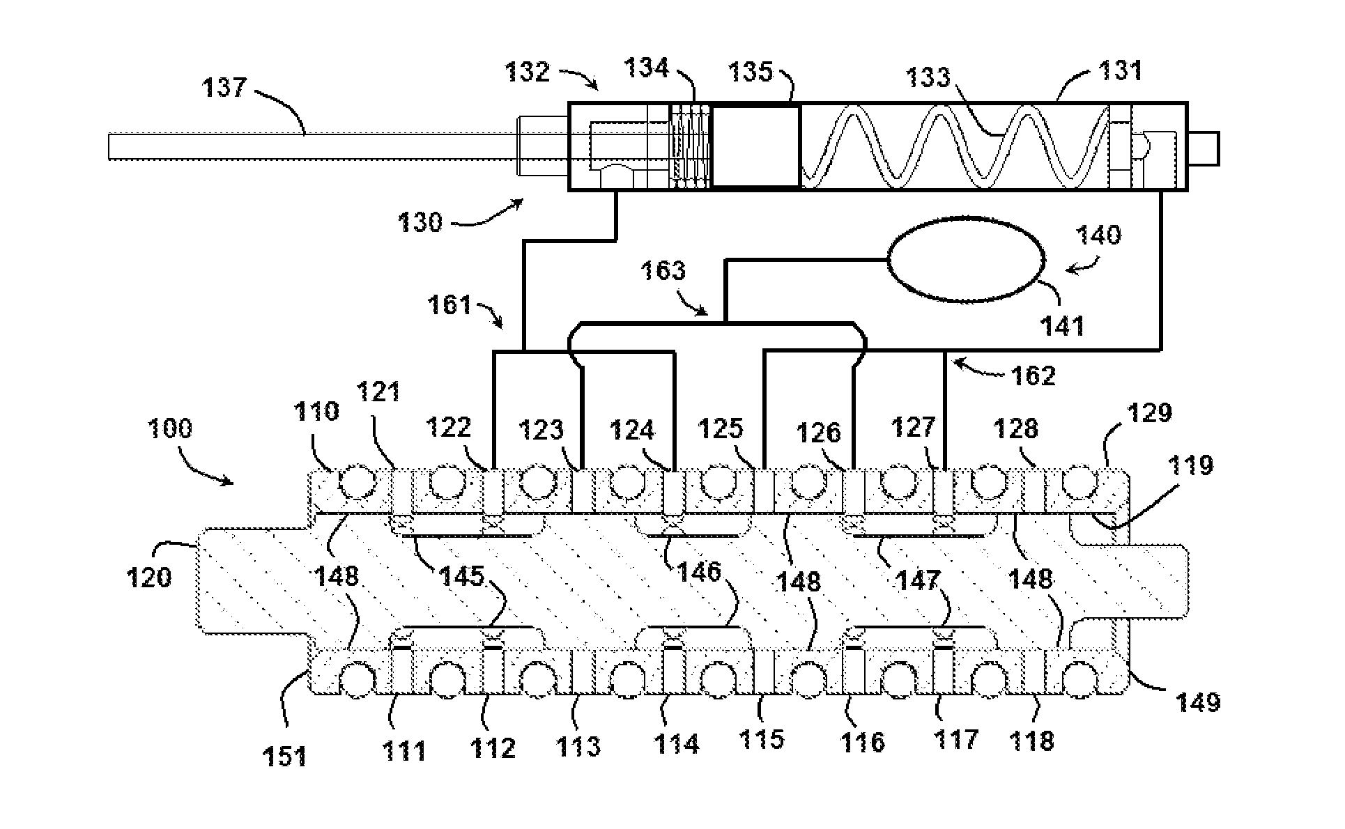
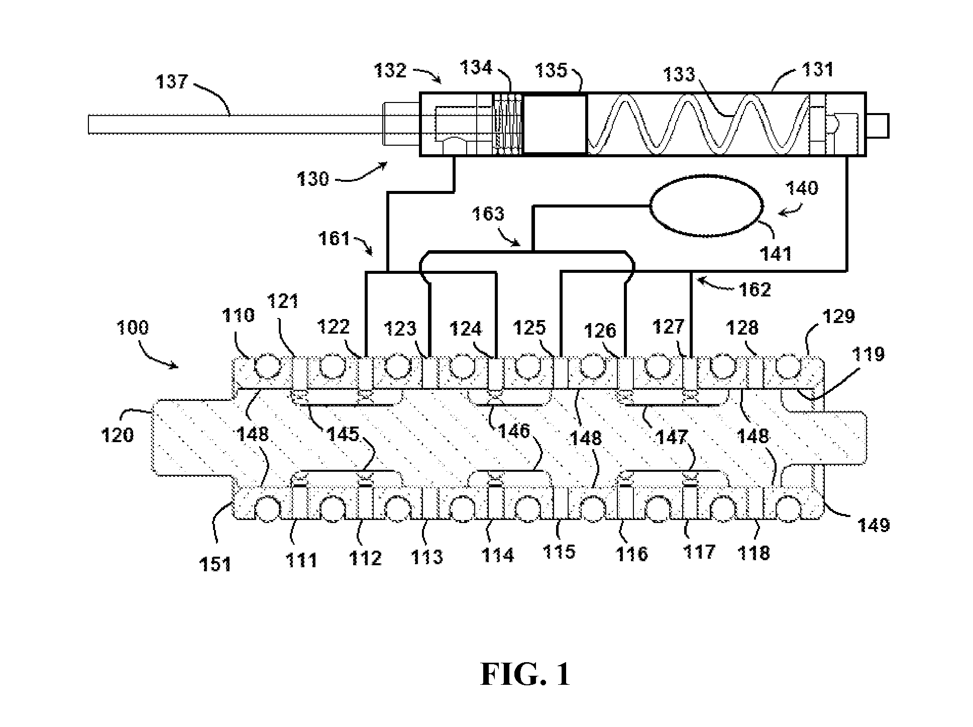
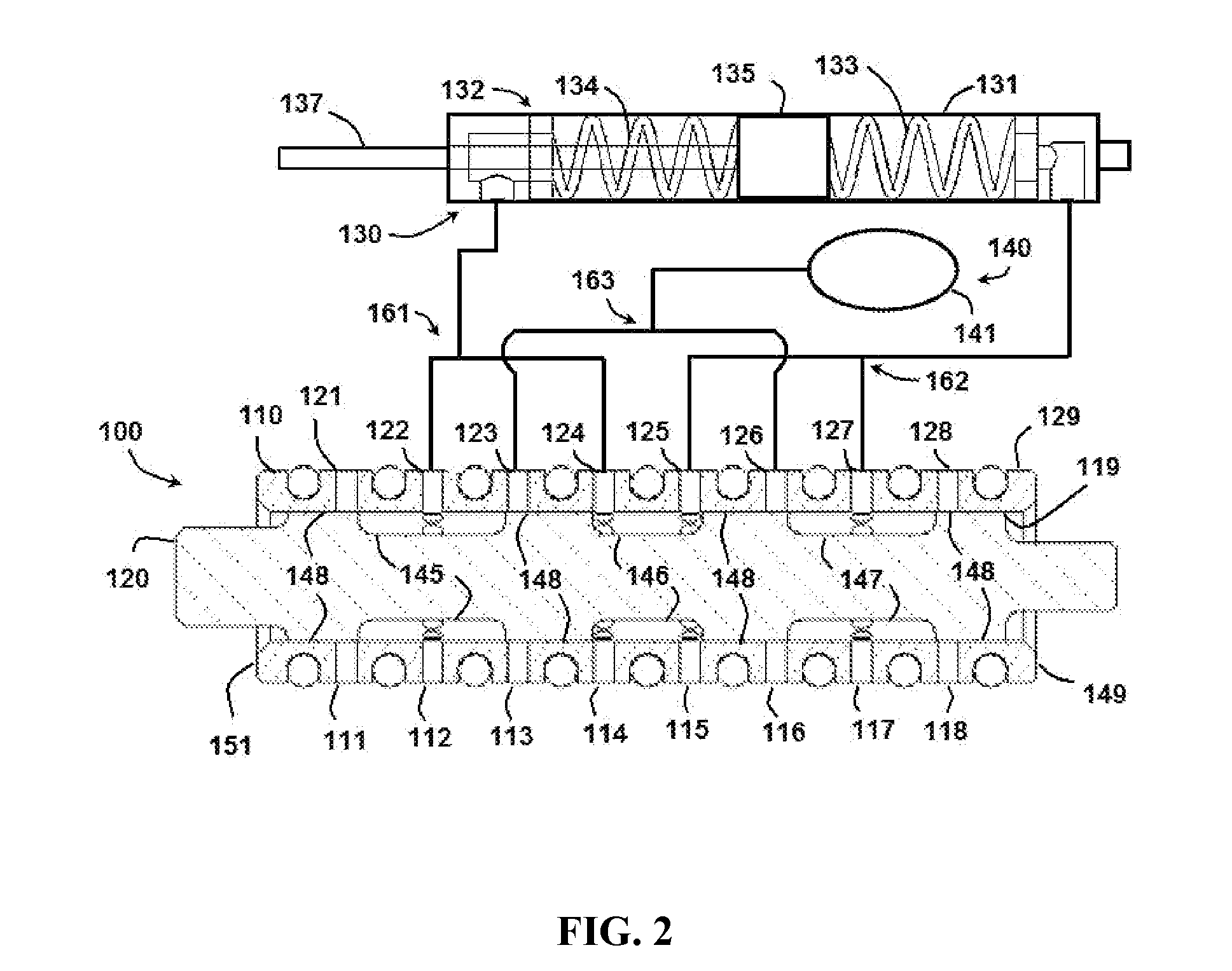
[0049]Referring now to FIGS. 1-3, an exemplary embodiment of this disclosure comprises a solenoid valve 100 comprising a sleeve or housing 110 and a sliding member or spool 120. In this embodiment, valve 100 is coupled to an actuator assembly 130 and a fluid supply system 140. In the embodiment shown, actuator assembly 130 comprises a casing 131, an actuator 132 (having a rod 137 and a piston 135), a first biasing member 133 and a second biasing member 134. In certain embodiments, first and second biasing members 133 and 134 may be compression springs. In the embodiment shown, piston 135 of actuator 132 divides a volume of fluid contained within casing 131 into two separate volumes (one on each side of piston 135). While a linear actuator is shown, other embodiments may comprise different configurations, such as a rotary actuator (not shown). Rotary actuator embodiments may comprise an actuator that separates the fluid contained within the casing into two volumes, with a first side ...


PUM


Abstract

A solenoid valve including a spool received within a housing. The spool is configured to move to multiple positions within the housing. The housing includes supply ports, exhaust ports, and outlet ports. When the spool is in a specific location, two outlet ports are in fluid communication with each other.

Description

STATEMENT REGARDING FEDERALLY SPONSORED RESEARCH OR DEVELOPMENT[0001]The government may own rights in this invention pursuant to grant numbers N660001-06-8005 JHUAPL from the Department of Defense.FIELD OF THE INVENTION[0002]The present disclosure relates generally to solenoid valve assemblies used to control the position of a fluid power actuator. The present disclosure relates more specifically to solenoid valve assemblies that recycle fluid from one portion of the actuator assembly to another portion of the actuator assembly.BACKGROUND INFORMATION[0003]Typical solenoid valve systems utilize a binary-type fluid power positioning system in which the solenoid valve is directed to one of two or three positions. In many existing two-position valves, the solenoid is coupled to an actuator assembly with a double-acting piston. When the solenoid valve is in the first position, air (or other fluid) is directed to one side of the piston, while air on the second (opposite) side of the pisto...

Claims


Application Information

Patent Timeline
Patent Type & Authority Applications(United States)
IPC IPC(8): F16K11/00F16K31/02
CPCF15B13/0402F16K31/0613F16K31/426F16K11/07Y10T137/87169Y10T137/86493F15B2013/0412F15B11/024F15B2211/3133F16K27/041F15B2211/3122F15B13/042
Inventor GOLDFARB, MICHAELSHEN, XIANGRONG
Owner VANDERBILT UNIV
Why Eureka
Try Eureka