
Pneumatic tire
a pneumatic tire and all-season technology, applied in the direction of non-skid devices, vehicle components, transportation and packaging, etc., can solve the problems of difficult to achieve both the driving stability on a wet road surface and the snow performance by using these tread patterns, so as to improve the driving stability of the pneumatic tire, avoid the decrease in the rigidity and avoid the effect of the first land portion's rigidity
- Summary
- Abstract
- Description
- Claims
- Application Information
AI Technical Summary
Benefits of technology
Problems solved by technology
Method used
Image

Examples
examples
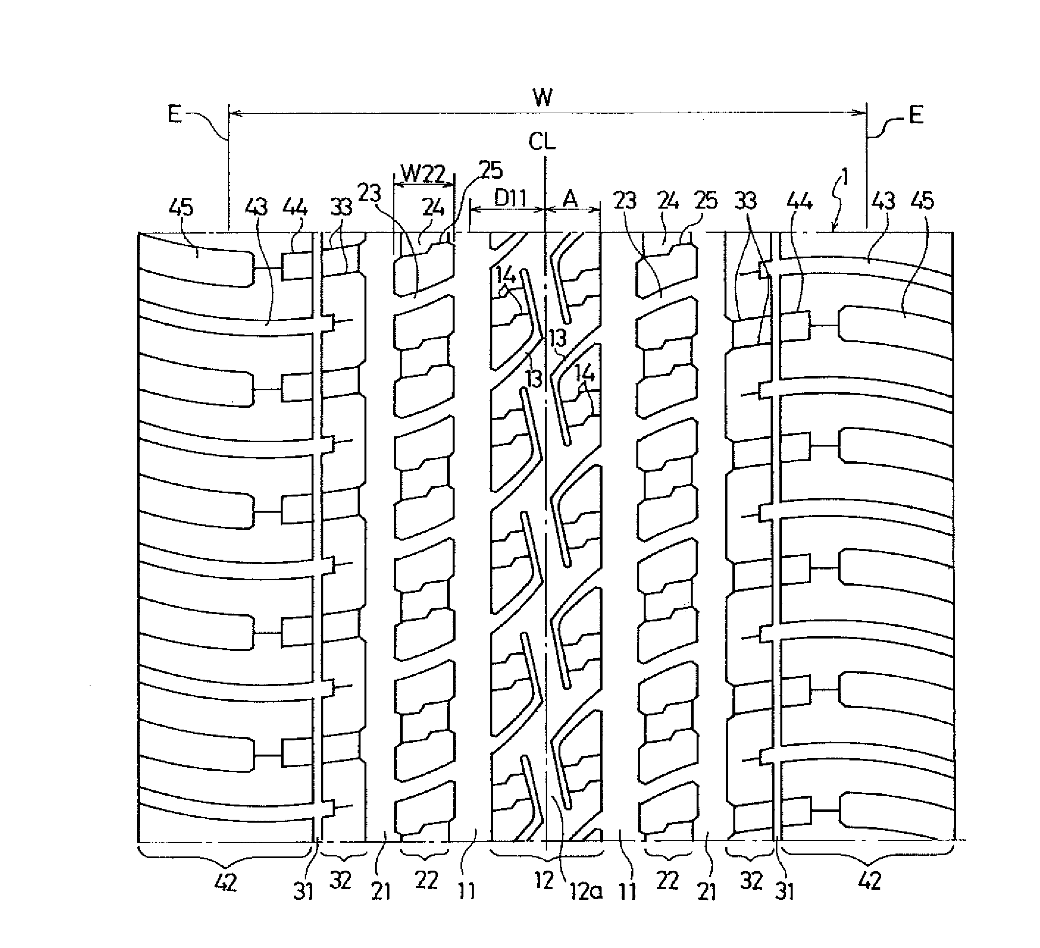
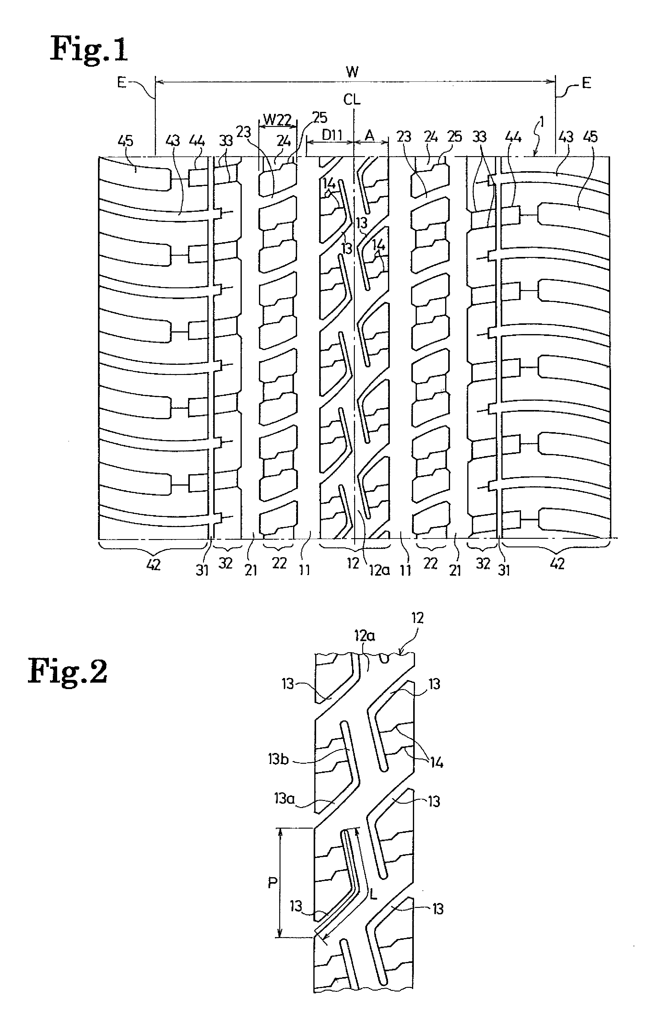
[0056]Pneumatic tires according to each of Examples 1 to 5 were made with a tire size of P265 / 70R17 113H (TRA), and with the tread pattern shown in FIG. 1, but by setting a ratio of the distance between the center position of each first main groove and the tire equator line to the ground contact width W (hereinafter referred to as a “location of first main groove”) as well as a ratio (L / P) of the length L of the center line of each sub-groove to the pitch length P of the sub-grooves in the tire circumferential direction as shown in Table 1.
[0057]Tires according to each of Comparative Examples 1 to 3 were prepared for the comparison purpose. The tires according to Comparative Example 1 had no sub-grooves. The tires according to Comparative Example 2 had sub-grooves, the two ends of each of which were opened to the two main grooves situated at the two sides of the first land portion, respectively. The tires according to Comparative Example 3 had the ratio (L / P) of the length L of the ...
PUM
 Abstract
Description
Claims
Application Information