
Apparatus and method for manipulating micro component

a micro-component and apparatus technology, applied in the direction of fluid pressure measurement, liquid/fluent solid measurement, peptides, etc., can solve the problems of inability to manufacture monolithic micromachining, and inability to manufacture critical components during assembly. , to achieve the effect of reducing capillary force, reducing dc voltage, and reducing dc voltag

Inactive Publication Date: 2011-01-13
THE UNIVERSITY OF AKRON
View PDF6 Cites 33 Cited by
  • Summary
  • Abstract
  • Description
  • Claims
  • Application Information

AI Technical Summary

Benefits of technology

The patent describes an apparatus and method for manipulating micro components using a gripper system. The apparatus includes a base substrate with electrodes, a dielectric layer, and a hydrophobic layer. The hydrophobic layer is made of a material that can change its behavior when an electric field is applied. By controlling the voltage and applying a liquid droplet to the hydrophobic layer, the apparatus can lift, hold, and release the micro component. The method involves transferring patterns to the substrate, etching the substrate, spin coating layers of dielectric and hydrophobic material, and curing the hydrophobic material. The technical effects of this invention include improved precision and control in manipulating micro components, as well as a simplified and efficient manufacturing process.

Problems solved by technology

However, more complex hybrid microsystems which have complex 3-D geometries and multiple micro components may use diverse materials and conflicting fabrication processes, and thus cannot be manufactured by monolithic micromachining.
This amount of force has a tendency to scratch or indent micro objects, and destroy critical features on the component during assembly.
In addition, the assembly of micro parts using conventional mechanical microgrippers can be hindered by undesired surface adhesion between a micro part and the gripper, caused by surface forces such as electrostatic forces, van der Waals forces, and capillary forces.
Optical tweezers have been used to trap nanoscale particles, but cannot generate large enough optical forces to trap objects with weights in the pNewton order.
One challenge for a capillary gripper is that, once an object is picked up, the capillary lifting force remains constant and the object is difficult to release.
All these release techniques require external actuation apparatus and increase the system complexity.

Method used


Image

  • Apparatus and method for manipulating micro component
  • Apparatus and method for manipulating micro component
  • Apparatus and method for manipulating micro component

Examples


Embodiment Construction

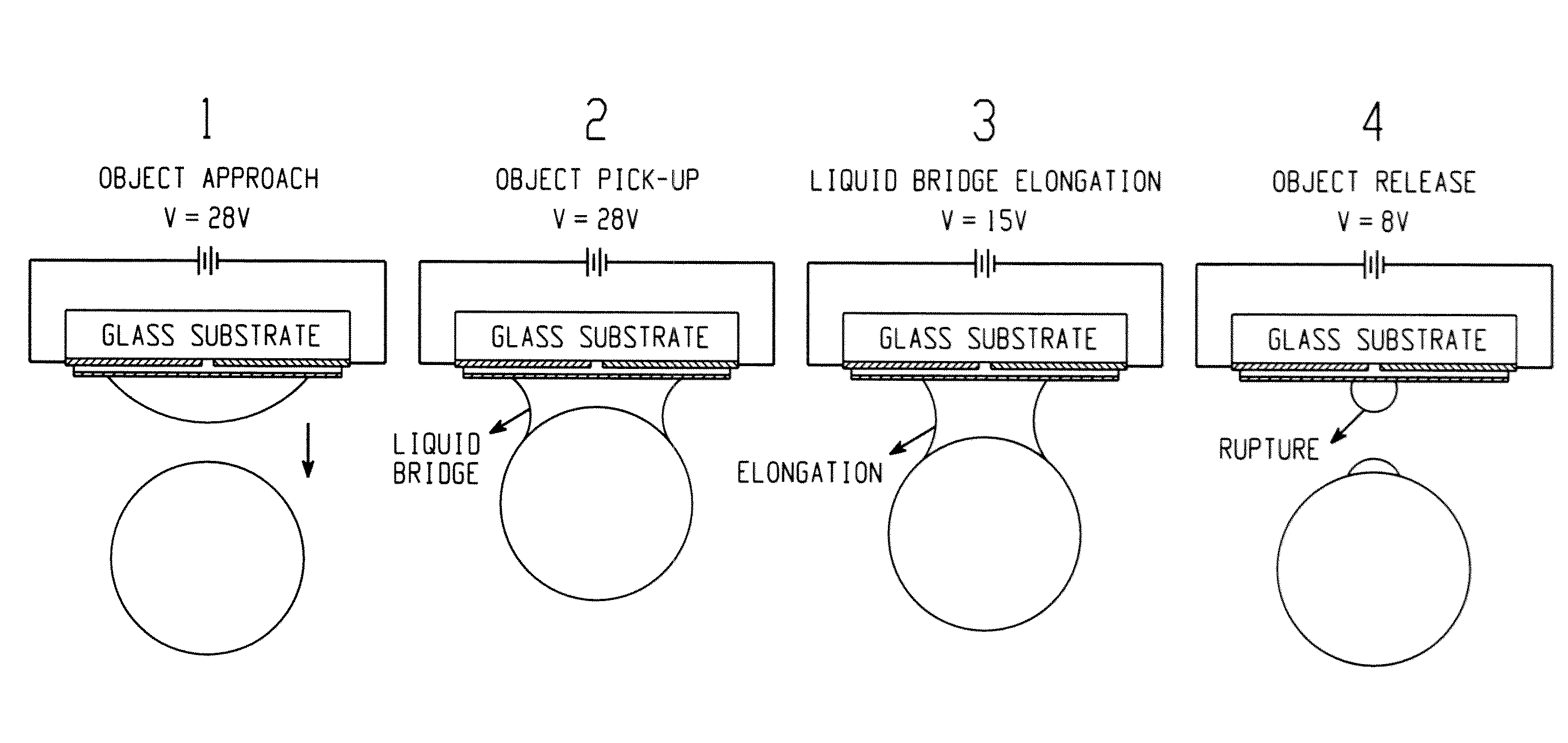
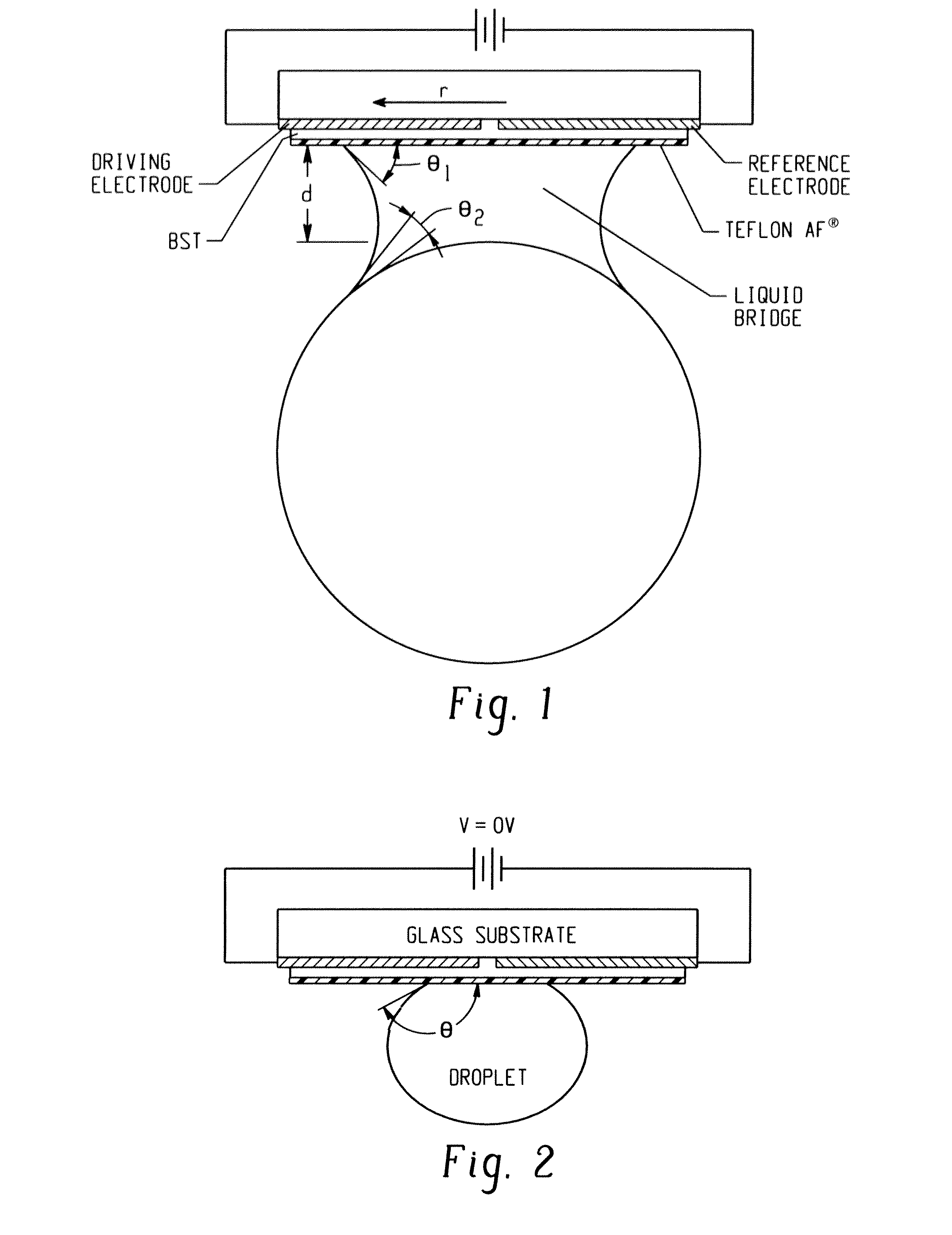
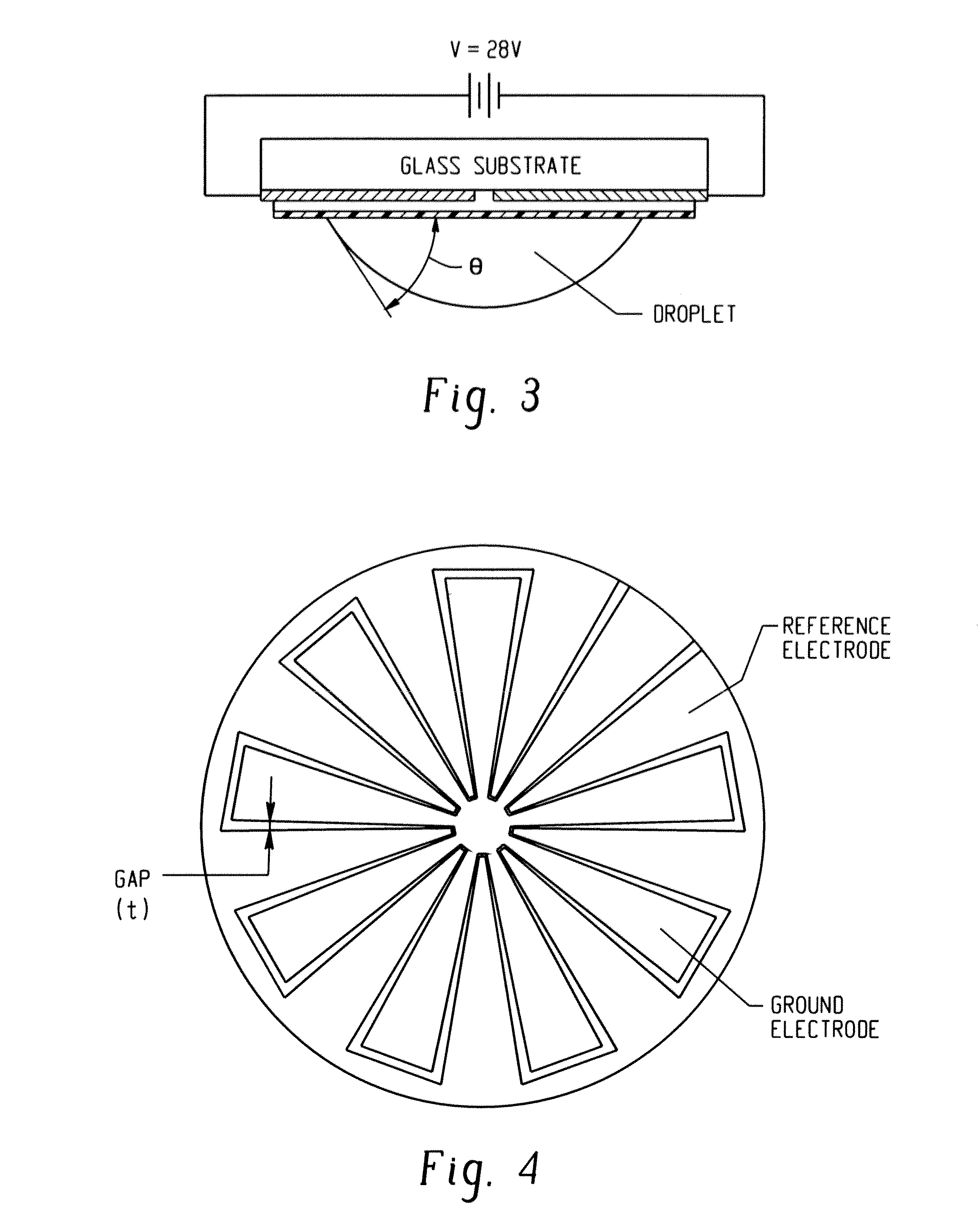
[0027]FIG. 16 is a flowchart of an exemplary embodiment of a process for manufacturing an exemplary embodiment of a gripper subsystem. Electrowetting is a phenomenon which is used to manipulate the contact angles of a liquid by application of an electric potential. Recent simulations have explored theoretical aspects of electrowetting and suggest the feasibility of dynamically adjusting capillary force induced by a liquid bridge. For additional information on the electrowetting simulation, see Chandra, A Numerical Study for Liquid Bridge Based Microgripping and Contact Angle Manipulation by Electrowetting Method, PhD Thesis, The University of Akron, December 2007, 232 pages, the contents of which are fully incorporated herein by reference. The exemplary embodiments described herein provide advancements to the electrowetting experiments modeled by Chandra and implement a capillary microgripper that, for example, can pick up and release micro glass beads by electrowetting. In one exem...


PUM

PropertyMeasurementUnit
lift voltageaaaaaaaaaa
thicknessaaaaaaaaaa
thicknessaaaaaaaaaa

Abstract

In one embodiment, a system for manipulation of a micro component includes a gripper subsystem for lifting, holding, and releasing a micro component. The gripper subsystem includes a base substrate having a work side and an opposing side, a positive electrode secured to the work side of the base substrate, a negative electrode suitably spaced from the positive electrode and secured to the work side of the base substrate, a dielectric layer formed over the work side of the base substrate and the positive and negative electrodes, and a hydrophobic layer comprising a hydrophobic material with predictable electrowetting behavior formed over the dielectric layer such that the dielectric layer is between the work side of the base substrate and the hydrophobic layer. A method for manipulation of a micro component is also provided as well as a method of manufacturing the system for manipulation of a micro component.

Description

CROSS REFERENCE TO RELATED PATENTS AND APPLICATIONS[0001]This application claims the right of priority and benefit of the earlier filing date of U.S. Provisional Patent Application Ser. No. 61 / 223,514, filed Jul. 7, 2009, the contents of which are fully incorporated herein by reference.BACKGROUND[0002]The present exemplary embodiment relates generally to manipulating a micro component by lifting, holding, and releasing the micro component while it is moved from an initial location to a destination location. It finds particular application in conjunction with fabrication of hybrid and complex microelectromechanical systems (MEMS). However, it is to be appreciated that the present exemplary embodiment is also amenable to manipulation of micro components for various purposes, including for other types of fabrication.[0003]Advancements in MEMS technology have led to the design of MEMS devices with complex structures and geometries. MEMS devices are generally fabricated by well establish...

Claims


Application Information

Patent Timeline
Patent Type & Authority Applications(United States)
IPC IPC(8): B01D57/02C23F1/02
CPCB81C99/002
Inventor ZHE, JIANGVASUDEV, ABHAY
Owner THE UNIVERSITY OF AKRON
Learn More