Container for filtering liquid having an outlet aperture for air

a technology of air outlet and container, which is applied in the direction of filtration separation, separation process, treatment involving filtration, etc., can solve the problems of no longer guaranteed contact, no filter material level, and flow problems

a technology of air outlet and container, which is applied in the direction of filtration separation, separation process, treatment involving filtration, etc., can solve the problems of no longer guaranteed contact, no filter material level, and flow problems

US20110005991A1Inactive Publication Date: 2011-01-13BRITA GMBH

Image

  • Container for filtering liquid having an outlet aperture for air
  • Container for filtering liquid having an outlet aperture for air
  • Container for filtering liquid having an outlet aperture for air

Examples


Embodiment Construction

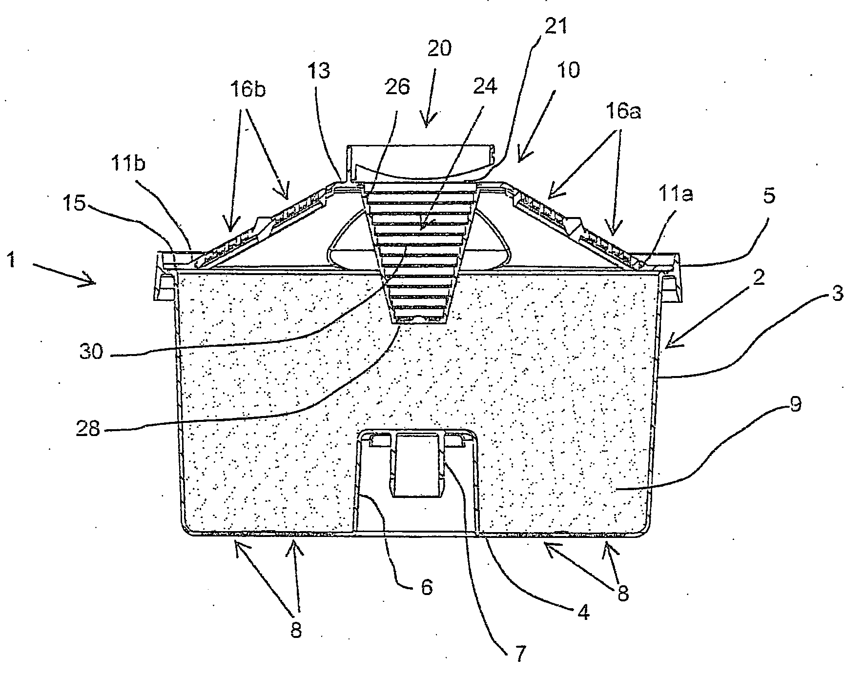
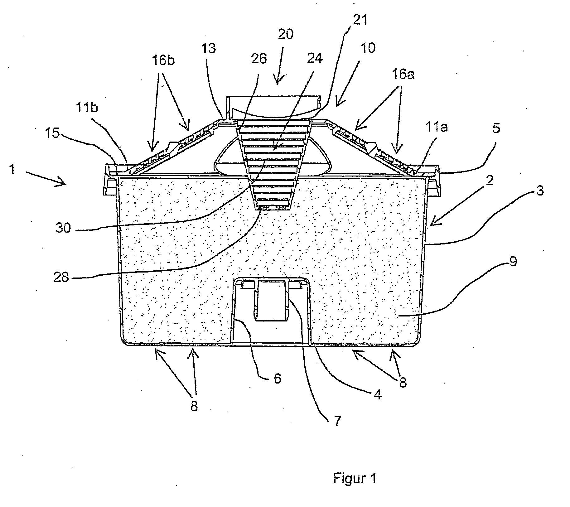
FIG. 1 shows a container 1, which has a cup 2 and a cover 10. The cup 2 has a bottom wall 4, a cup edge 5, which also can be used as a sealing edge, and a circumferential wall 3, and it is filled with filter material 9. The bottom wall 4 has a recess 6 with a fixation element 7 arranged on the inside, by which the container 1 can be fastened in a water funnel (not shown). The bottom wall 4, moreover, has water outlet windows 8, which are provided with a lattice-like structure, which prevents the filter material 9 from escaping downward into a container (not shown) that receives the filtered water.

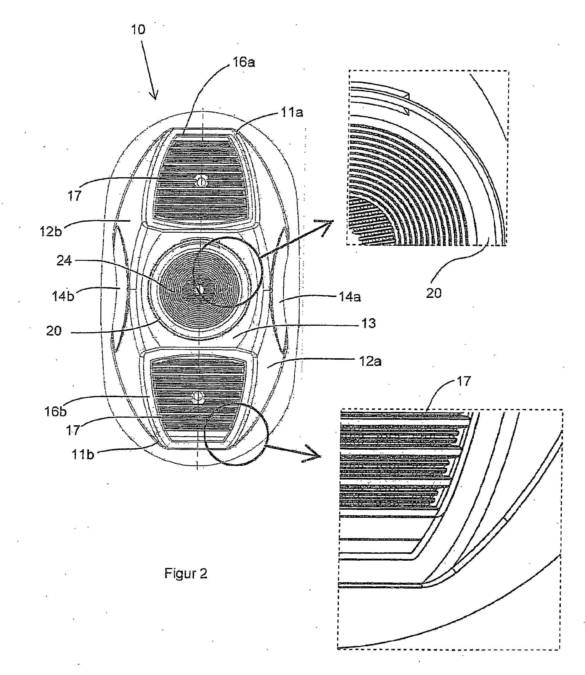
The cover 10 is curved on top and fashioned as a hood, and in the representation shown here it has a roughly trapezoidal cross section with window walls 11a, 11b and a cover wall 13. In the window walls 11a, 11b are arranged water inlet windows 16a, 16b, through which the water being filtered flows into the container 1. An air outlet window 20 is arranged in the middle of the cover wall 13 ...


PUM

PropertyMeasurementUnit
lattice structureaaaaaaaaaa
lattice structuresaaaaaaaaaa
shapeaaaaaaaaaa

Abstract

A container for the filtration of liquid is described, which has a cup and a cover mounted on the cup. The cup is at least partly filled with a filter material and has at least one outlet window for the liquid. The cover has at least one inlet window and at least one outlet window for air, wherein at least the windows have lattice-like structures with lattice openings. The air outlet window has at least one recess extending inward from the plane of the window, which is provided at least partially with at least one lattice structure.

Description

FIELD OF THE INVENTIONThe invention concerns a container for the filtration of liquid, with a cup, which is at least partly filled with a filter material and has at least one outlet window for the liquid, and with a cover mounted on the cup, which has at least one inlet window for the liquid and at least one outlet window for air, wherein at least the inlet window and the air outlet window have lattice-like structures with lattice openings.BACKGROUND OF THE INVENTIONSuch containers are also known as filter cartridges, and they are generally used in gravity-operated filter devices. Such filter devices are primarily used in the household, especially for filtration of water.The filter cartridges are loaded with filter materials, especially in granular form.In the filter device, the filter cartridges are inserted into a water funnel, into which the water being filtered is poured. The water funnel is placed in a jug, which catches the filtered water.The filter cartridges are only tempora...

Claims


Application Information

Patent Timeline
13 Jan 2011
Publication
US20110005991A1
IPC
B01D35/30
CPC
C02F1/003; C02F2307/04; C02F2201/006; C02F1/006
Inventors
MERZ, ALEXANDRA; GUCKES, GUNDER