Motor

a motor and motor body technology, applied in the field of motors, can solve the problems of increasing the number of parts used and complicating the operation of assembling the brushless motor, and achieve the effect of reducing the number of parts and facilitating the assembly of the motor

Active Publication Date: 2011-01-13
NIPPON DENSAN CORP
View PDF16 Cites 38 Cited by
  • Summary
  • Abstract
  • Description
  • Claims
  • Application Information

AI Technical Summary

Benefits of technology

[0008]In a motor according to a preferred embodiment of the present invention, a bearing holder is defined in a busbar holder. Therefore, it is possible to assemble the motor with a bearing already held in the busbar holder. This contributes to reducing the number of parts, and makes it easy to assemble the motor.

Problems solved by technology

However, the provision of the connector fittings between the windings and the externally projecting pin results in an increased number of parts used when assembling the brushless motor.
The increased number of parts thus involves an increased number of welding points, which complicates an operation of assembling the brushless motor.

Method used


Image

  • Motor
  • Motor
  • Motor

Examples


Embodiment Construction

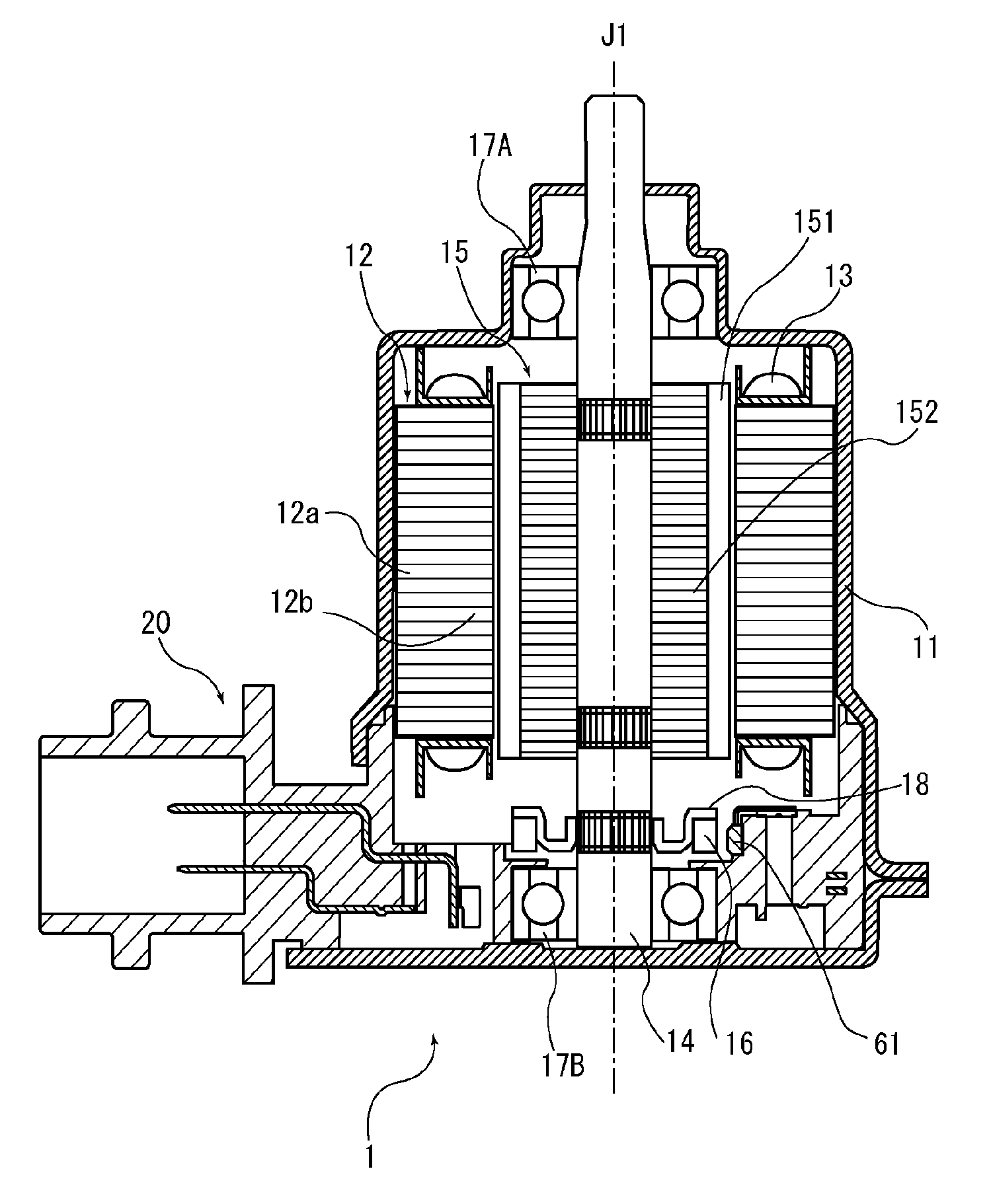
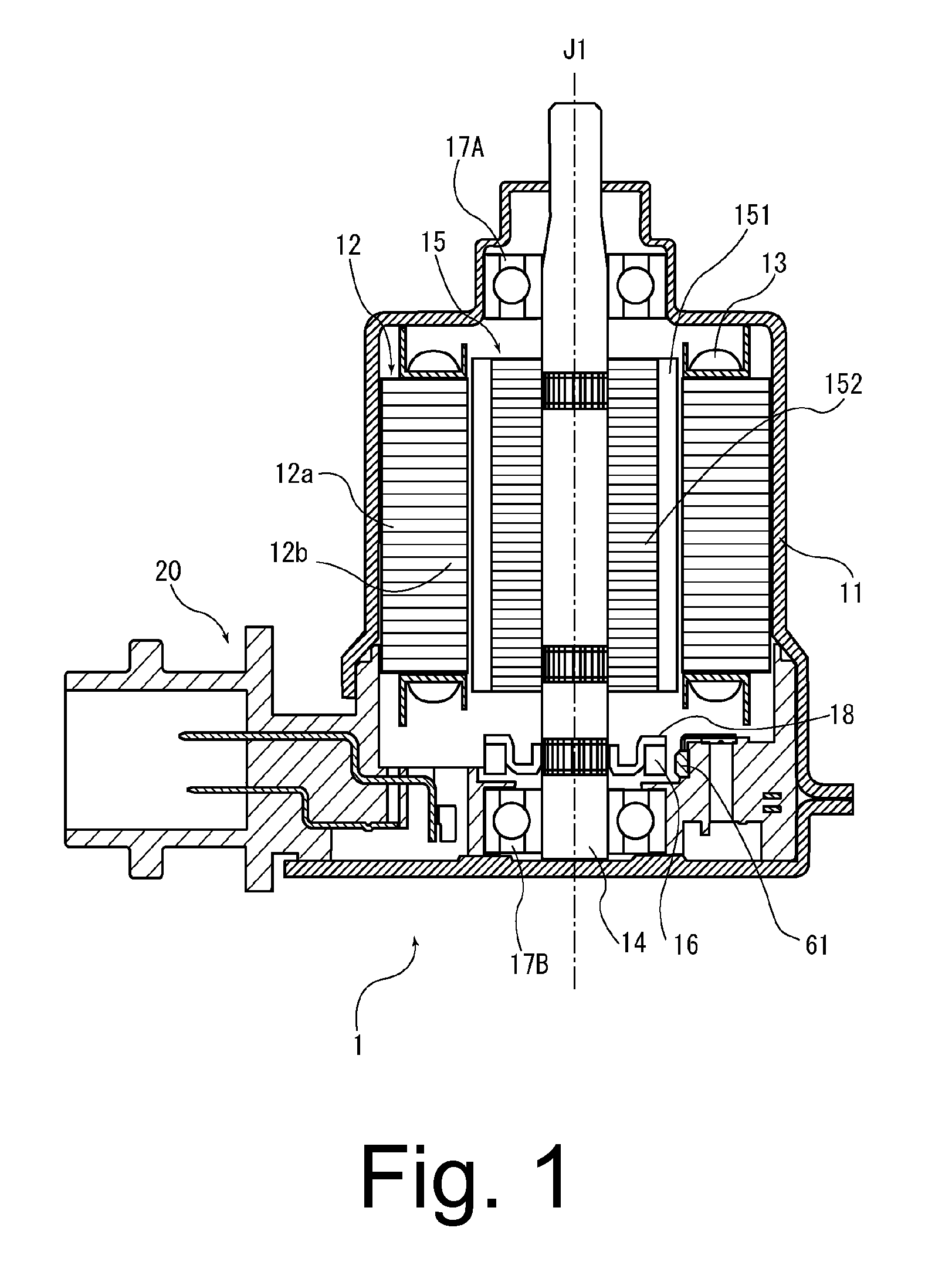
[0028]Hereinafter, preferred embodiments of the present invention will be described with reference to the accompanying drawings. FIG. 1 is a side cross-sectional view of a brushless motor 1 according to a preferred embodiment of the present invention. The brushless motor 1 illustrated in FIG. 1 includes a housing 11, a stator core 12, coils 13, a shaft 14, a rotor 15, a sensor magnet 16, and a busbar unit 20. The brushless motor 1 is used, for example, to select a gear of a transmission installed on a vehicle, or to drive a clutch. The brushless motor 1 is driven through an electrical current supplied from a power supply unit (not shown), such as, for example, a battery, through a control unit (not shown), such as, for example, an ECU.

[0029]The brushless motor 1 may be installed in an apparatus in various manners depending on the apparatus, and also may be arranged in various orientations. Therefore, no absolute upward / downward directions exist for the brushless motor 1. However, fo...


PUM


Abstract

In a busbar unit, which is a distributing device arranged to supply electrical currents to coils, a busbar holder is arranged to support coil connection busbars and sensor connection busbars. A bottom surface portion of a busbar holder body portion includes a bearing holder holding a bearing defined therein, and includes resistors and capacitors defining a portion of a Hall IC circuit arranged thereon. The Hall IC circuit is arranged to input and output electrical signals to or from Hall ICs. An upper surface portion includes sensor holders each holding a separate one of the Hall ICs defined therein. A connector portion is arranged to project radially outward from the busbar holder body portion. The sensor connection busbars and each of the coil connection busbars are arranged one above another along an axial direction.

Description

BACKGROUND OF THE INVENTION[0001]1. Field of the Invention[0002]The present invention relates to a motor.[0003]2. Description of the Related Art[0004]JP-A 2007-006592 discloses a conventional brushless motor in which a drive current is supplied to each coil without the use of a busbar, with a view to achieve a reduction in the size of the brushless motor. Specifically, an insulator covering a stator is arranged to support connector fittings which serve as terminals of windings. In addition, an externally projecting pin arranged to establish electrical continuity between an inside and an outside of the motor is supported by a bearing holder. The windings and the externally projecting pin are connected to the connector fittings by welding.[0005]As described above, the brushless motor disclosed in JP-A 2007-006592 is structured such that the drive current is supplied to each coil without the use of a busbar, in order to achieve a reduction in size.[0006]However, the provision of the co...

Claims


Application Information

Patent Timeline
Patent Type & Authority Applications(United States)
IPC IPC(8): H02K5/22H02K5/16H02K11/00
CPCH02K3/522H02K29/08H02K5/225
Inventor FUJII, YOSHIOFUJIHARA, HISASHIHAMAGISHI, KENICHIROYAMADA, YOSUKE
Owner NIPPON DENSAN CORP
Why Eureka
Try Eureka