Solid state lighting device with improved heatsink

Active Publication Date: 2011-01-13
IDEAL IND LIGHTING LLC
View PDF16 Cites 82 Cited by
  • Summary
  • Abstract
  • Description
  • Claims
  • Application Information

AI Technical Summary

Problems solved by technology

High power solid state emitters can draw large currents, thereby

Method used


Image

  • Solid state lighting device with improved heatsink
  • Solid state lighting device with improved heatsink
  • Solid state lighting device with improved heatsink

Examples


Embodiment Construction

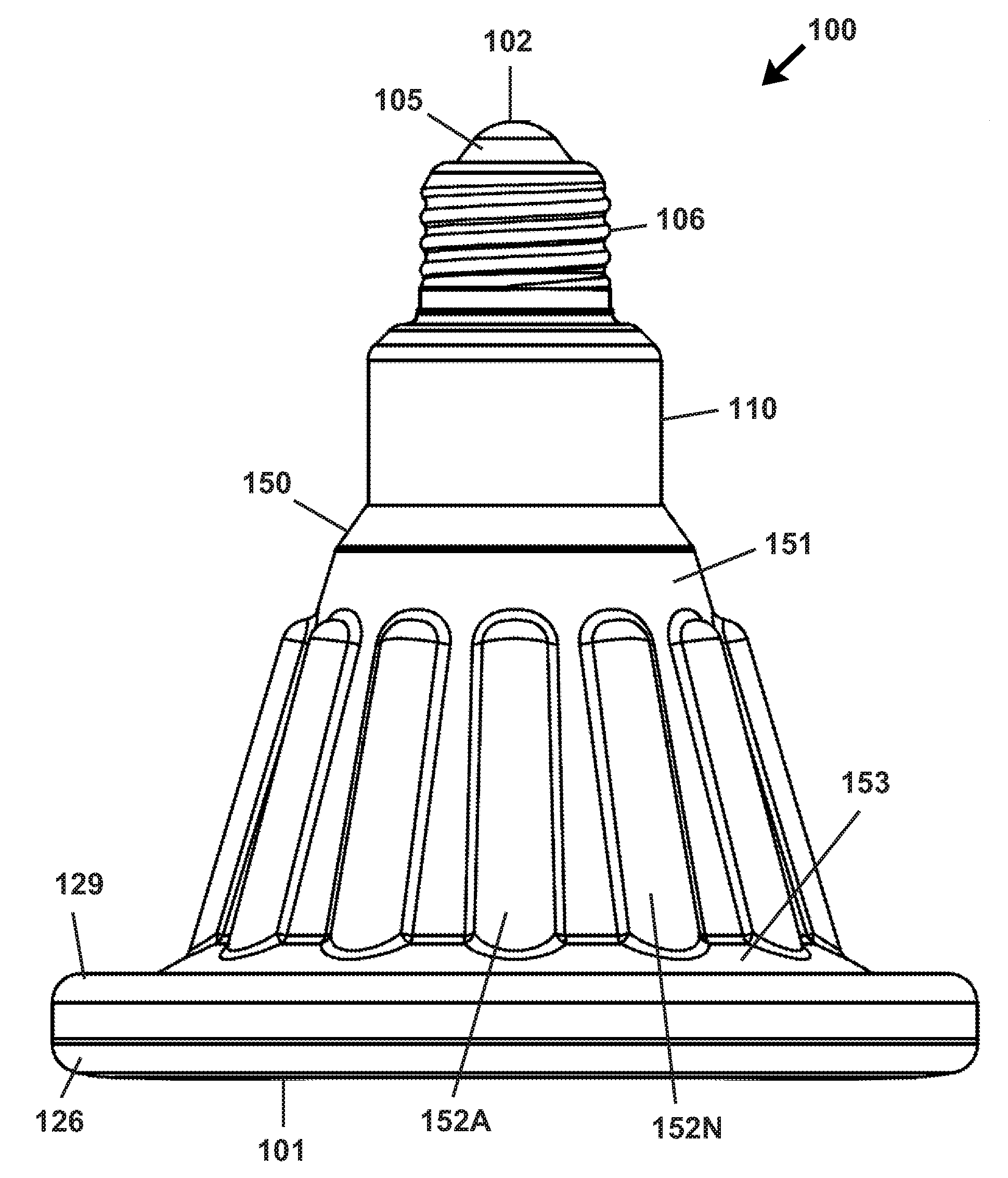
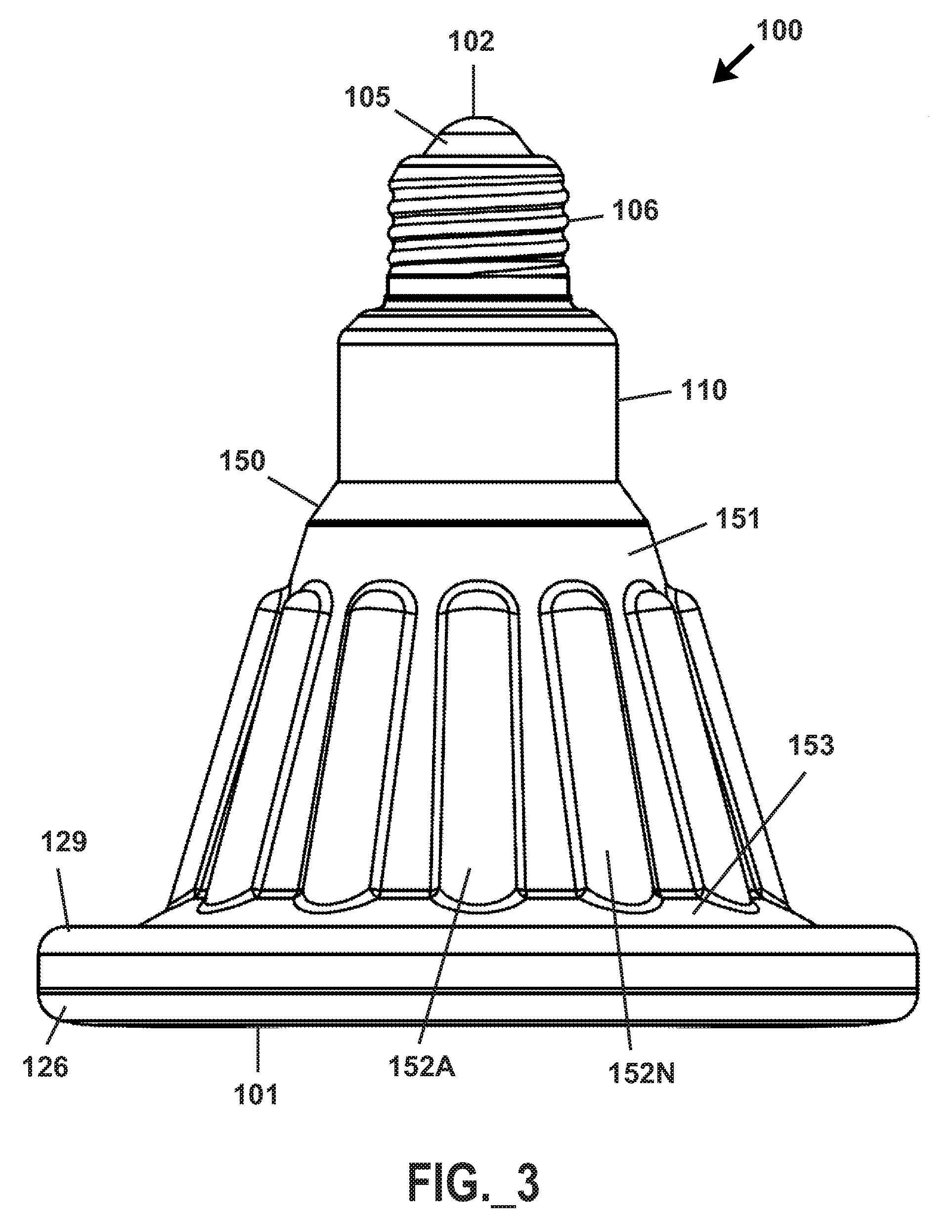
[0022]The present invention relates in one aspect to a lighting device comprising at least one solid state emitter and a forged heatsink in thermal communication with the at least one solid state emitter. The present invention further relates to methods of fabricating solid state light emitting devices including forged heatsinks, and methods for illuminating a space or object utilizing a lighting device comprising at least one solid state device and a forged heatsink in thermal communication therewith.

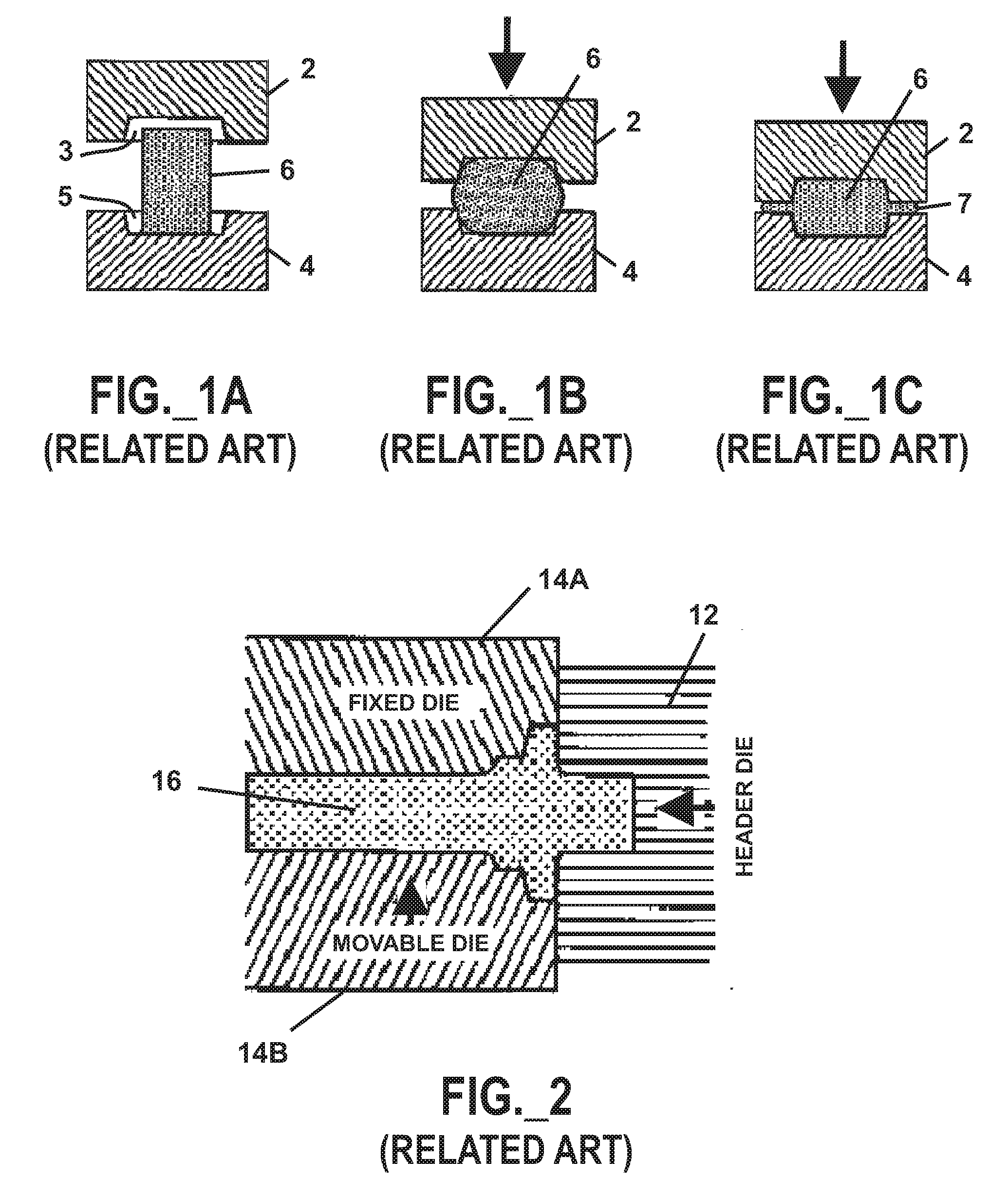
[0023]As mentioned previously, solid state lighting devices commonly employ cast, extruded, and / or machined aluminum heatsinks along one or more exposed outer surfaces of such devices. Although casting, extrusion, and machining methods have heretofore been used successfully to produce heatsinks for solid state lighting devices, recent introduction of high power solid state devices and imposition of packaging constraints caused Applicants to investigate alternative designs and fabricati...


PUM


Abstract

A solid state lighting device includes at least one emitter and a forged heatsink arranged to receive and dissipate heat generated by emitter(s). The heatsink may have a thickness and/or profile that varies in at leats two dimensions. Fabrication of a solid state lighting device may include providing a forged heatsink, and mounting at least one solid state emitter in thermal communication with the heatsink. A space or object may be illuminated with a lighting device including at least one solid state emitter and a forged heatsink. The lighting device may be operated responsive to at least one sensor arranged to sense temperature and/or at least one characteric of light emitted by the emitter(s).

Description

FIELD OF THE INVENTION[0001]The present invention relates to solid state lighting devices, and heat transfer structures relating to same.DESCRIPTION OF THE RELATED ART[0002]Solid state light sources may be utilized to provide white light (e.g., perceived as being white or near-white), and have been investigated as potential replacements for white incandescent lamps. Light perceived as white or near-white may be generated by a combination of red, green, and blue (“RGB”) emitters, or, alternatively, by combined emissions of a blue light emitting diode (“LED”) and a yellow phosphor. In the latter case, a portion of the blue LED emissions pass through the phosphor, while another portion of the blue LED emissions is “downconverted” to yellow; the combination of blue and yellow light provide a white light. Another approach for producing white light is to stimulate phosphors or dyes of multiple colors with a violet or ultraviolet LED source. A solid state lighting device may include, for e...

Claims


Application Information

Patent Timeline
IPC IPC(8): H01J7/24H01J9/00
CPCB21K21/10F21V29/004F21V29/773F21Y2101/02F21K9/137F21V29/006F21K9/233F21Y2115/10F21V29/51
Inventor CHAN, WAI KWANDARLEY, DEREK IANVAN DE VEN, ANTONY PAULNEGLEY, GERALD H.
Owner IDEAL IND LIGHTING LLC
Why Eureka
Try Eureka