Method and Apparatus for Determining the Best Blending of Overlapped Portions of Projected Images

Active Publication Date: 2011-01-13
SEIKO EPSON CORP
View PDF13 Cites 19 Cited by
  • Summary
  • Abstract
  • Description
  • Claims
  • Application Information

AI Technical Summary

Benefits of technology

[0012]Each smoothness qualities pair can be plotted as a point in an X-Y Cartesian coordinate system wit

Problems solved by technology

However, none of the prior art seems to disclose a method for determining a “

Method used


Image

  • Method and Apparatus for Determining the Best Blending of Overlapped Portions of Projected Images
  • Method and Apparatus for Determining the Best Blending of Overlapped Portions of Projected Images
  • Method and Apparatus for Determining the Best Blending of Overlapped Portions of Projected Images

Examples


Example

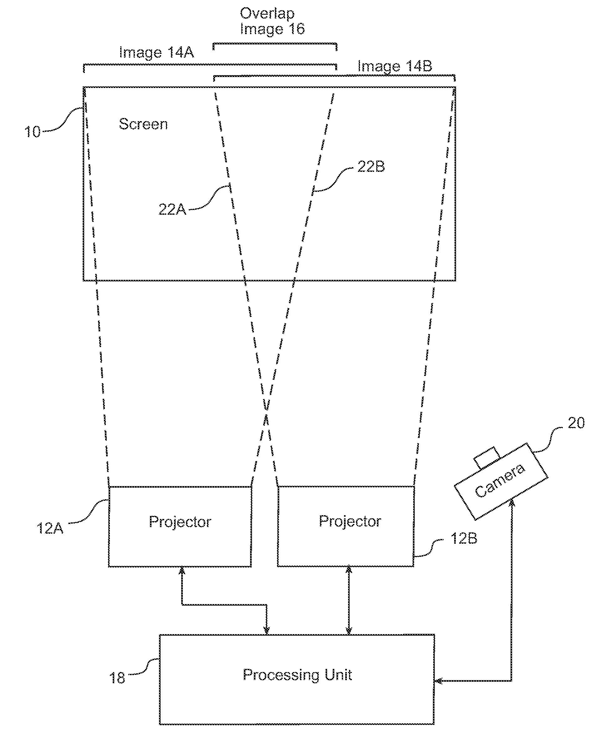
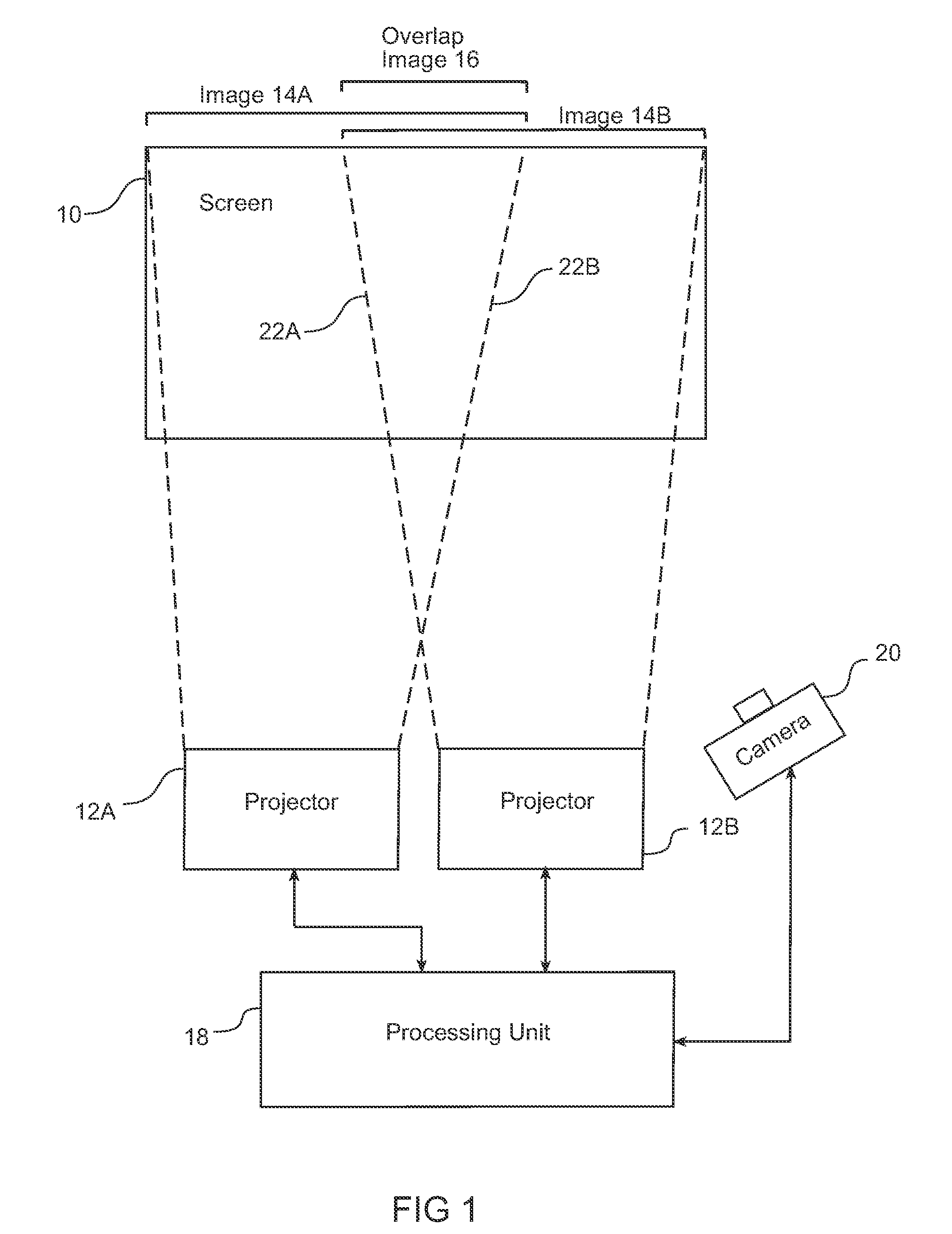
[0020]FIG. 1 shows a general system block diagram of the environment of the present invention. In this system, multiple projectors are controlled and coordinated to provide a large display region such as a wall display. In FIG. 1, just two projectors are illustrated for simplicity; however, in a large system three, four, or more projectors may be utilized. As shown, projectors 12A and 12B each project an image onto a portion of the screen 10, with image 14A occupying one portion, image 14B occupying a second portion, and overlap image 16 occupying a portion that represents the intersection of images 14A and 14B projected onto screen 10. Using multiple projectors in this manner with overlapping and complementary projections can be used to provide a very large, but still very bright and clear, continuous display.

[0021]Various approaches are available to build the multi-projector display of FIG. 1. It is well known that in order to project what appears to be a single continuous image, ...


PUM


Abstract

A best blending function from among a plurality of blending functions is determined. Each of the plurality of blending functions smoothes an overlap region of at least two projected images. The overlap image is captured and a processing unit analyzes the stored overlap image for color value linearity to calculate a first smoothness result. The processing unit analyzes the projection of the first or second image for color value uniformity to calculate a second smoothness result. These smoothness results for one blending function are paired and compared to smoothness result pairs corresponding to other blending functions to determine a best blending function from among those being analyzed.

Description

BACKGROUND[0001]The present invention is related to a multiple projector system. In this system multiple projectors are controlled and coordinated to provide a large display region such as a wall display. In such a display the goal is to provide a seamless image. However, in certain areas there is an overlap region where two projectors contribute light output to the same portion of the display surface. Unfortunately the combination from two projectors in this overlap region is additive and results in a brighter region with color differences. The overlap region is thus a visible band in the overall displayed image.[0002]In order to minimize the visual band that occurs from the overlap region, a number of techniques have been proposed to “blend” the image to reduce the visual differences from one region to another. A simple blending method would output pixels in the overlapping edge regions of projector A and B at only 50% of their source brightness. Or, similarly, another simple meth...

Claims


Application Information

Patent Timeline
IPC IPC(8): H04N5/228G06K9/36H04N9/74H04N9/31
CPCH04N9/3147H04N9/3197H04N9/3194
Inventor MICELI, SEAN
Owner SEIKO EPSON CORP
Why Eureka
Try Eureka