Lighting device, display device and television receiver

a technology of display device and light source, which is applied in the field of light source device, display device and television receiver, can solve the problems of increasing the cost of backlight device, increasing the number of lamps, and increasing power consumption

Inactive Publication Date: 2011-01-13
SHARP KK
View PDF24 Cites 5 Cited by
  • Summary
  • Abstract
  • Description
  • Claims
  • Application Information

AI Technical Summary

Benefits of technology

[0009]The present invention was made in view of the foregoing circumstances. An object of the present invention is to provide a lighting device in which light emitted from a light source is effectively used to ensure uniform brightness and achieve a cost reduction and power saving. Another object of the present invention is to provide a display device including such a lighting device and a television receiver including such a display device.
[0012]According to such a configuration, one or two of the first end portion, the second end portion and the middle portion are configured as the light source installation areas in which the light source is arranged, and the rest is configured as the empty area in which no light source is arranged. Therefore, compared to a case in which the light sources are arranged evenly in the entire chassis, the number of light sources is reduced and a cost reduction and power saving of the lighting device can be achieved.
[0014]However, according to the present invention, the optical member that is provided so as to cover the opening of the chassis has the portion that overlaps the light source installation area at least a surface of which faces the light source has a relatively high light reflectance. Moreover, the light reflectance of at least the surface of the portion that overlaps the empty area facing the light source is relatively low. Accordingly, light that comes from the light source installation area first reaches the portion of the optical member having the relatively high light reflectance. Therefore, most of the light reflects off the portion, that is, does not pass through the portion), and the brightness of illumination light is suppressed with respect to the light emission amount from the light source. On the other hand, the reflected light is further reflected within the chassis and reaches the empty area. The light reflectance of the portion of the optical member that overlaps the empty area is relatively low and thus a larger amount of light passes therethrough. As a result, predetermined brightness of illumination light is achieved.
[0015]Thus, the light emitted from the light source arranged in the light source installation area is reflected within the chassis by the portion of the optical member having the relatively high light reflectance is directed to the empty area. The light reflectance of the optical member is relatively low in the empty area to output the illumination light from the empty area where no light source is installed. As a result, the light sources are not required to be arranged in the entire lighting device, and therefore a cost reduction and power saving can be achieved.

Problems solved by technology

However, if the linear light is not sufficiently converted into the planer light, striped lamp images are generated along the alignment of the fluorescent tubes, and this deteriorates display quality of the liquid crystal display device.
However, increase of the number of lamps increases a cost of the backlight device and also increases power consumption.
Increase of the diffusion rate of the diffuser plate fails to improve luminance and causes the problem that the number of lamps is required to be increased.
That is, if the number of lamps arranged in the peripheral part of the display screen is excessively reduced, the lamp image may be generated.
Therefore, the configuration of Patent Document 1 does not sufficiently respond to the request of power saving of recent liquid crystal display devices, and further consideration has been needed.

Method used


Image

  • Lighting device, display device and television receiver
  • Lighting device, display device and television receiver
  • Lighting device, display device and television receiver

Examples


first embodiment

[0041]The first embodiment of the present invention will be explained with reference to FIGS. 1 to 8.

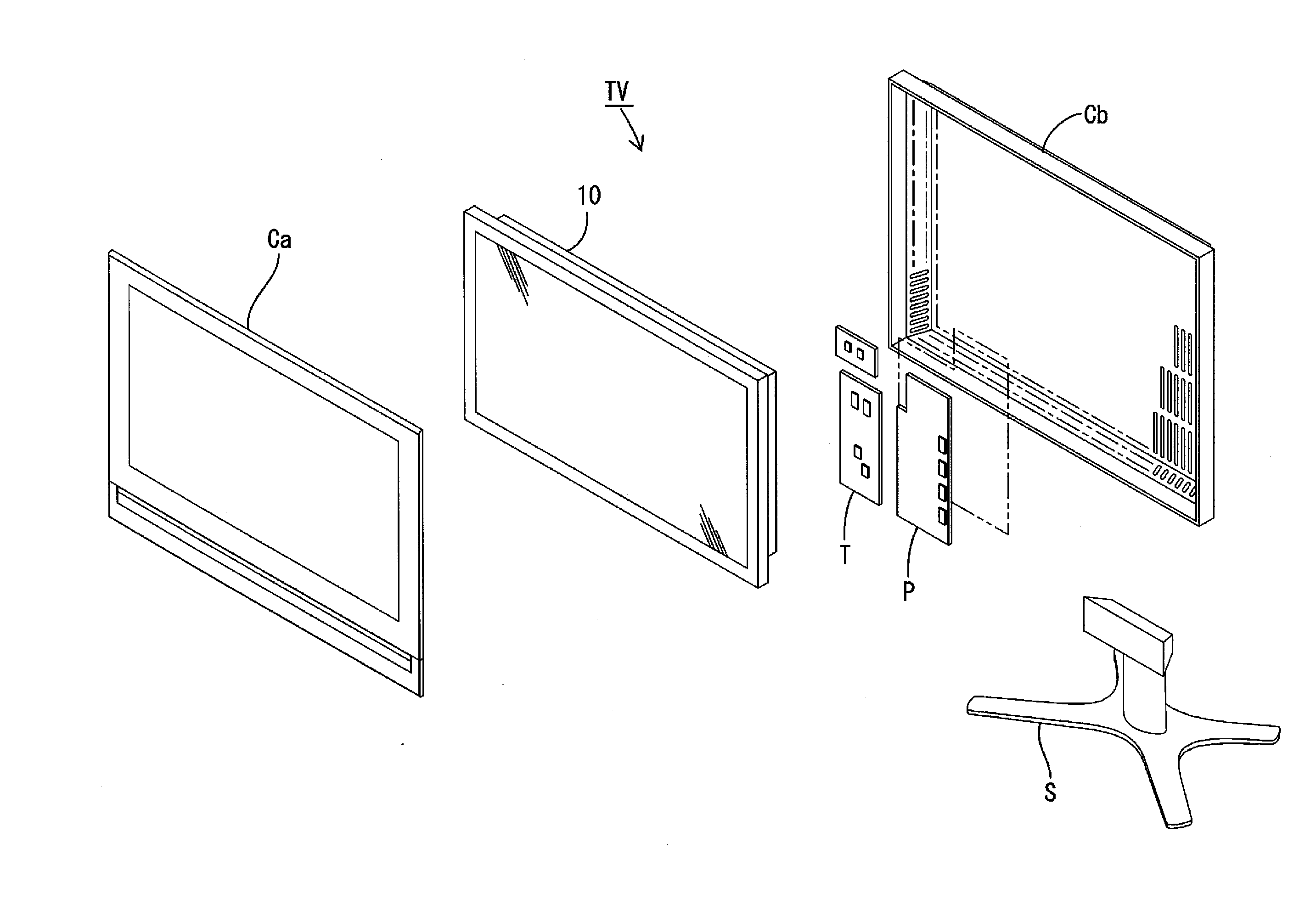
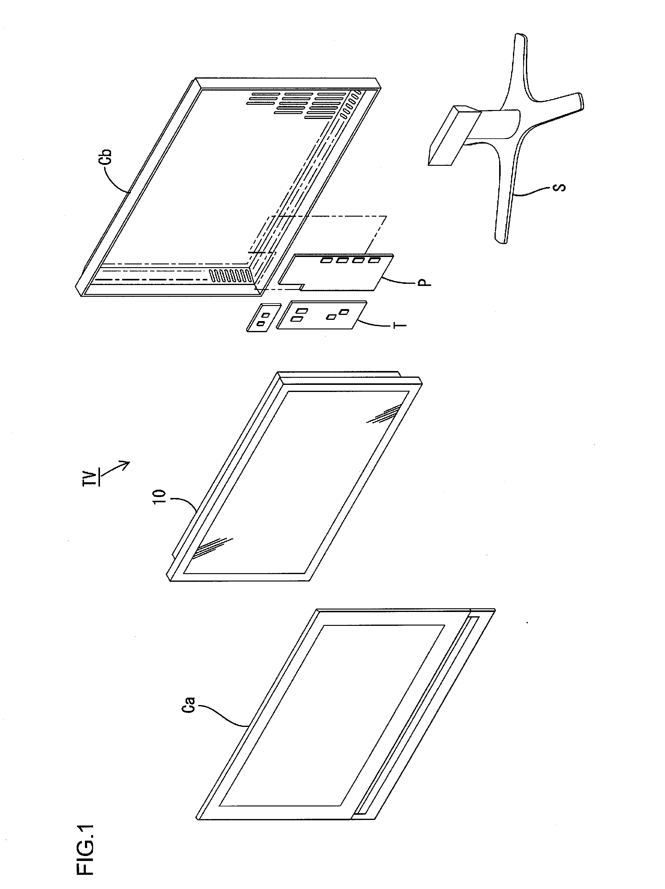
[0042]First, a construction of a television receiver TV including a liquid crystal display device 10 will be explained.

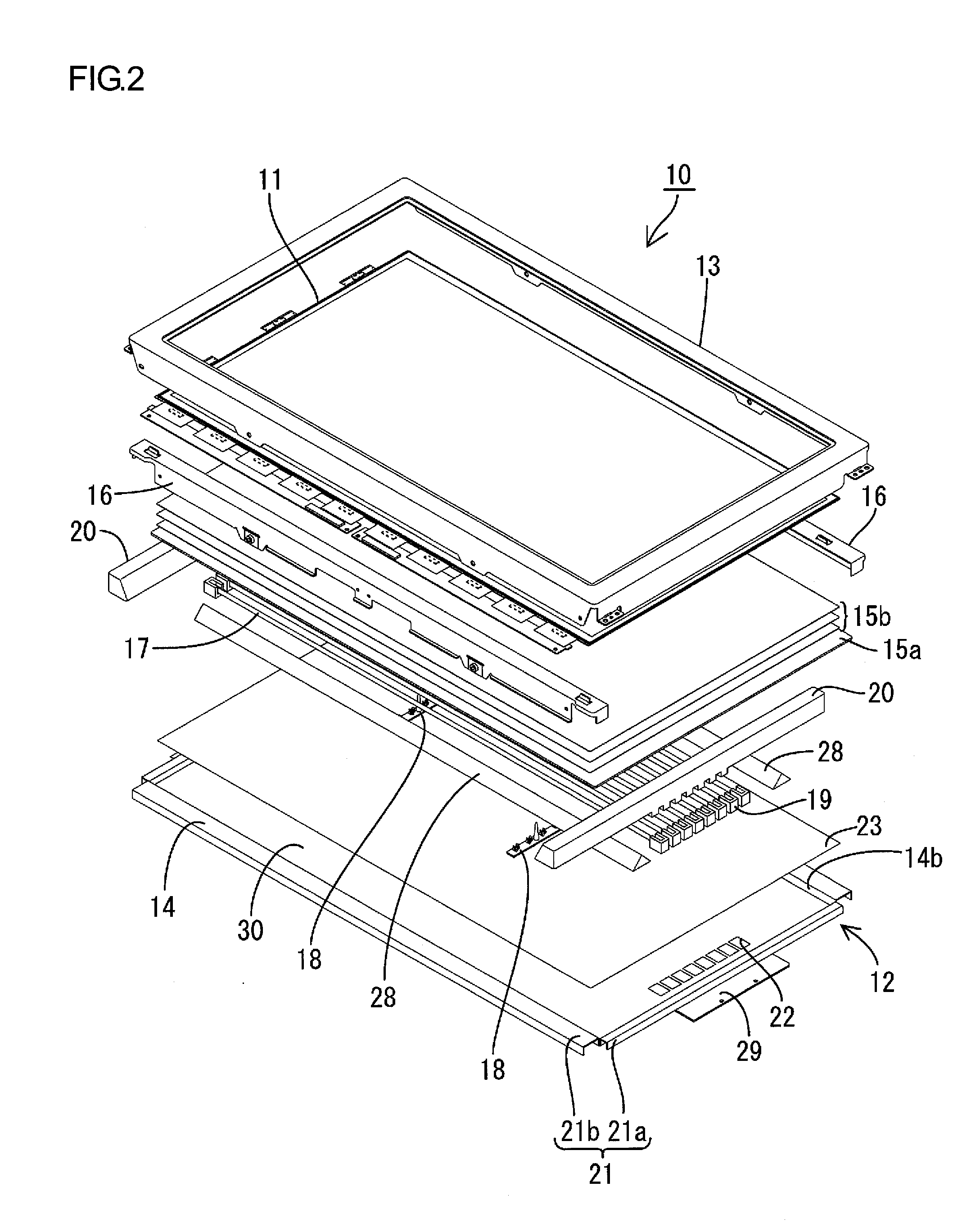
[0043]FIG. 1 is an exploded perspective view illustrating a general construction of the television receiver of this embodiment. FIG. 2 is an exploded perspective view illustrating a general construction of the liquid crystal display device included in the television receiver in FIG. 1. FIG. 3 is a cross-sectional view of the liquid crystal display device in FIG. 2 along the short-side direction. FIG. 4 is a cross-sectional view of the liquid crystal display device in FIG. 2 along the long-side direction. FIG. 5 is a plan view illustrating a general construction of a chassis included in the liquid crystal display device in FIG. 2. In FIG. 5, the long-side direction of the chassis is referred to as an X-axis direction and the short-side direction of the chassis is refe...

first modification

[0091]A first modification of the backlight device 12 according to the present embodiment will be explained with reference t o FIGS. 9 and 10. In this modification, the distribution of light reflectance of the diffuser plate is changed.

[0092]FIG. 9 is a plan view illustrating light reflectance of a surface of the diffuser plate facing the cold cathode tubes according to one modification. FIG. 10 is a graph illustrating a reflectivity change in the short-side direction of the diffuser plate in FIG. 9.

[0093]As illustrated in FIGS. 9 and 10, the light source overlapped portion DA of a diffuser plate 150a (a surface of the portion that overlaps the light source installation area LA facing the cold cathode tubes 17) has the highest light reflectance, and in the empty area overlapping surface DN of the diffuser plate 150a (a surface of the portion that overlaps the empty area LN facing the cold cathode tubes 17), the light reflectance decreases in a stepwise manner from the portion closer...

second modification

[0097]A second modification of the backlight device 12 according to the present embodiment will be explained with reference to FIGS. 11 and 12. The distribution of light reflectance of the diffuser plate is further modified in this modification.

[0098]FIG. 11 is a plan view illustrating light reflectance of a surface of the diffuser plate facing the cold cathode tubes according to another modification. FIG. 12 is a graph illustrating a reflectivity change in the short-side direction of the diffuser plate in FIG. 11.

[0099]As illustrated in FIGS. 11 and 12, a diffuser plate 250a is configured such that the light reflectance is lower at the ends than the middle portion in its short-side direction (Y-axis direction). Namely, in the entire diffuser plate 250a, the light reflectance of the light source overlapped portion DA (a surface of the portion that overlaps the light-source installation area LA facing the cold cathode tubes 17) that is located at its middle portion is relatively high...


PUM

PropertyMeasurementUnit
diameteraaaaaaaaaa
distanceaaaaaaaaaa
distanceaaaaaaaaaa

Abstract

A lighting device 12 of the present invention includes a light source 17, a chassis 14 configured to house the light source 17 and having an opening 14b for light from the light source 17 to pass through, and an optical member 15a provided so as to face the light source 17 and cover the opening 14b. The chassis 14 has a surface facing the optical member 15a. The surface includes at least a first end portion 30A, a second end portion 30B, and a middle portion 30C located between the first end portion 30A and the second end portion 30B. One or two of the first end portion 30A, the second end portion 30B and the middle portion 30C are configured as light source installation areas LA in each of which the light source 17 is arranged, and the rest is configured as an empty area LN in which no light source 17 is arranged. The optical member 15a has a portion that overlaps the light source installation area LA at least a surface of which faces the light source 17 has a light reflectance higher than a light reflectance of at least a surface of a portion that overlaps the empty area LN facing the light source 17.

Description

TECHNICAL FIELD[0001]The present invention relates to a lighting device, a display device and a television receiver.BACKGROUND ART[0002]A liquid crystal panel included in a liquid crystal display device does not emit light, and thus a backlight device is required as a separate lighting device. The backlight device is arranged behind the liquid crystal panel (i.e., on a side opposite from a display surface side). It includes a chassis having an opening on a liquid crystal panel side, a plurality of fluorescent tubes accommodated in the chassis as lamps, and an optical member (diffuser plate and the like) provided at the opening of the chassis for efficiently directing light emitted from the fluorescent tubes to a liquid crystal panel.[0003]In such a backlight device where the fluorescent tubes emit linear light, a plurality of fluorescent tubes are aligned with each other and the optical member converts linear light into planer light to unify illumination light. However, if the linea...

Claims


Application Information

Patent Timeline
Patent Type & Authority Applications(United States)
IPC IPC(8): H04N3/12F21V11/00F21S4/00G02F1/13357G02F1/1335
CPCG02F1/133611G02F1/133608
Inventor TAKATA, YOSHIKI
Owner SHARP KK
Why Eureka
Try Eureka