
Support shell arrangement for arrangement at a lower leg

a technology for supporting shells and lower legs, applied in the field of supporting shell arrangements for arrangement at lower legs, to achieve the effect of high operating and wearing comfort and sufficient rigidity

Active Publication Date: 2011-01-13
OPED
View PDF6 Cites 47 Cited by
  • Summary
  • Abstract
  • Description
  • Claims
  • Application Information

AI Technical Summary

Benefits of technology

[0006]Therefore, it is an object of the present invention to suggest a support shell arrangement that, one the one hand, enables a preferably air-permeable, i.e. well ventable, structure as well as high operating and wearing comfort and, on the other hand, exhibits a sufficient degree of rigidity so as to enable the formation of an articulated connection between the calf part and the foot part without the need for utilizing metallic structural parts.

Problems solved by technology

In particular during utilization of metallic fitting parts at support shell arrangements it has proven to be disadvantageous that, for performing X-ray examinations of the body parts received in the support shell arrangements, it is regularly necessary to remove the support shell arrangement from the body part due to the impermeability of the metallic parts to X-ray radiation.

Method used


Image

  • Support shell arrangement for arrangement at a lower leg
  • Support shell arrangement for arrangement at a lower leg
  • Support shell arrangement for arrangement at a lower leg

Examples


Embodiment Construction

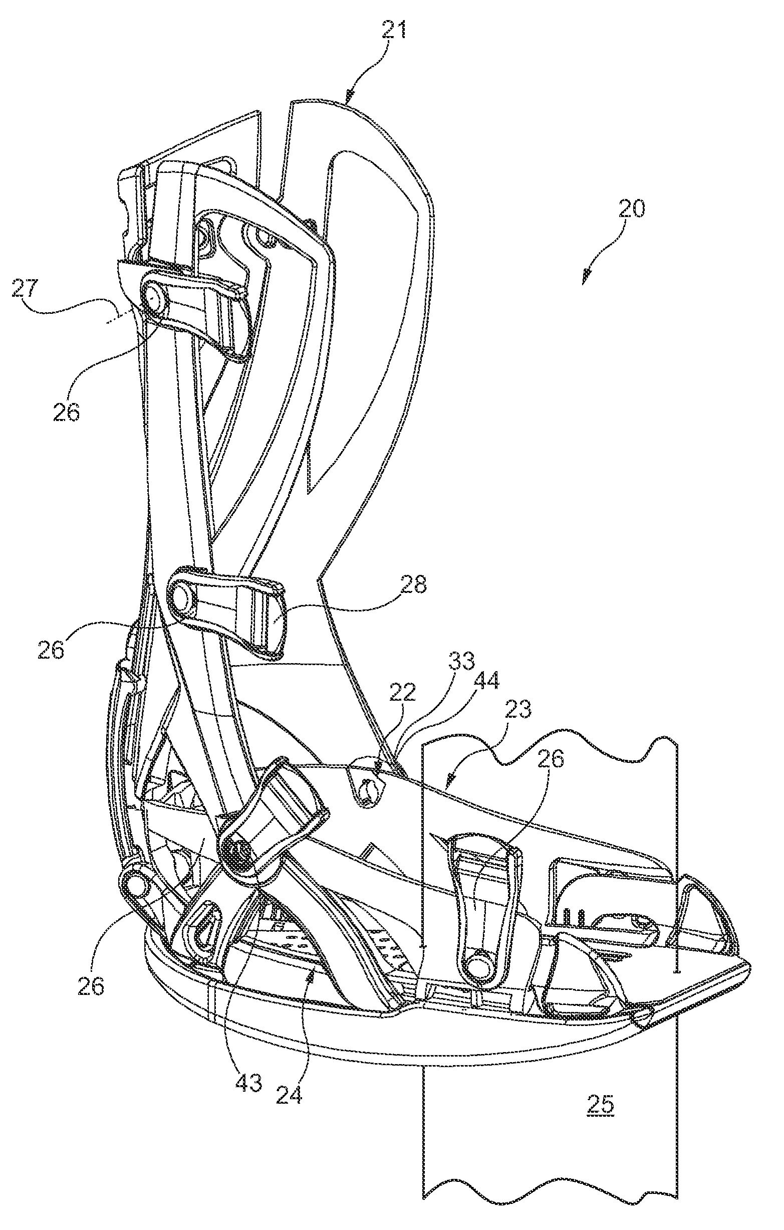
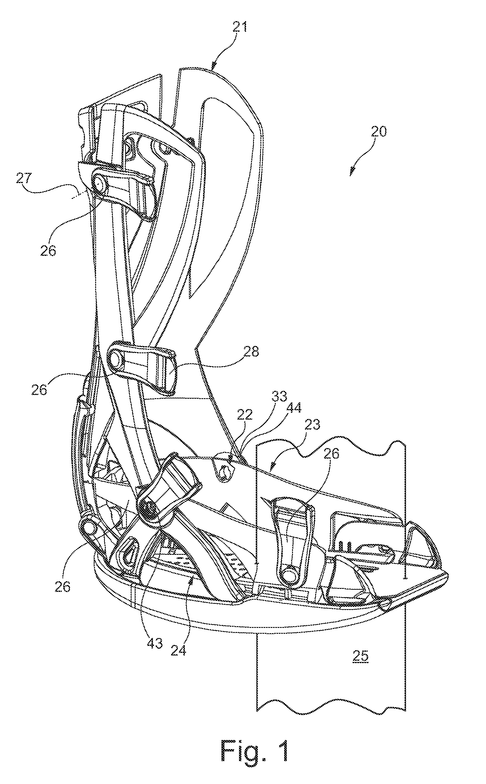
[0036]Referring to the drawings in particular, FIG. 1 shows a support shell arrangement 20 having a calf part 21 for receiving a lower leg and a foot part 23 connected to the calf part 21 via an articulated arrangement 22. The foot part 23 is provided with a support shell arrangement 24 that is articulately connected to the calf part 21 equally via the articulated arrangement 22.

[0037]To permit force-fitting arrangement of the support shell arrangement 20 at a patient's lower leg, both at the calf part 21 and at the foot part 23 provision is made for strap flaps 26 on both sides of a foot center plane 25 indicated in FIG. 1, which, for the sake of providing a clear overview, are only illustrated on the visible side of the foot center plane but, however, are also disposed in a mirror-inverted fashion on the invisible side of the foot center plane 25. The strap flaps 26 are connected to the calf part 21 and the foot part 23 respectively, so as to be swivelable about a flap axis 27 and...


PUM


Abstract

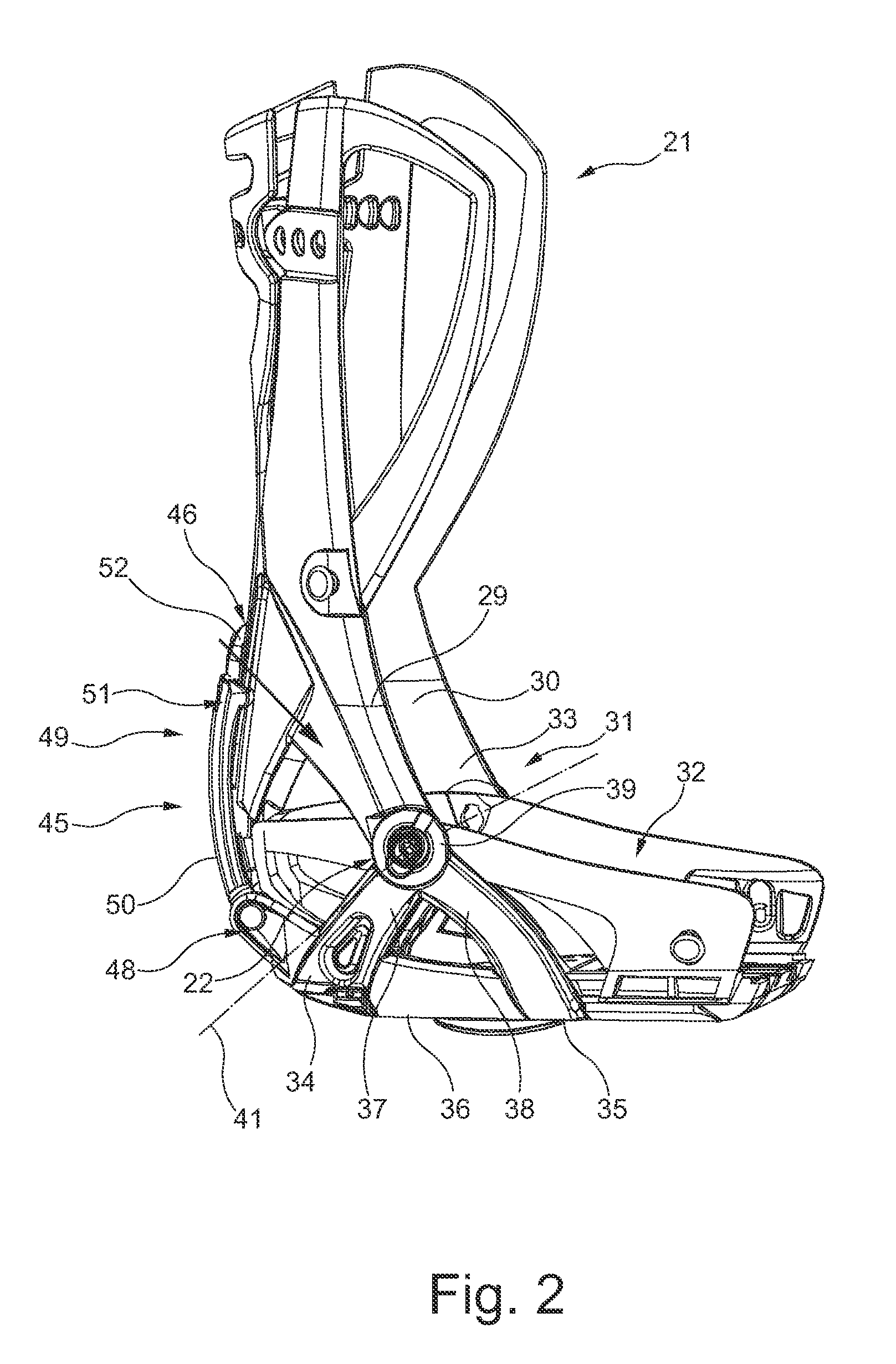
A support shell arrangement (20) is provided for arranging on a lower leg, having a foot part (23) and a calf part (21). The calf part includes two calf struts (29, 30) disposed at the side of an entry opening (32) of the calf part, extending in the longitudinal axis of the calf part, and a heel strut connected to the calf struts in a strut connection and extending toward a heel part of the foot part. A support bow arrangement (24) has two bow struts (34, 35) extending in a U-shape about a sole area, the free strut ends thereof being pivotally connected in pairs in a common pivot joint (43, 44) on a joint axis corresponding to the ankle joint and connected to a calf strut, and connected to each other in a V-shape by a common support basis (36). The support basis is pivotally connected to the heel strut of the calf part at the heel side end thereof.

Description

CROSS REFERENCE TO RELATED APPLICATIONS[0001]This application is a United States National Phase application of International Application PCT / EP2009 / 001392 and claims the benefit of priority under 35 U.S.C. §119 of German Patent Application DE 10 2008 013 382.5 filed Mar. 10, 2008, the entire contents of which are incorporated herein by reference.FIELD OF THE INVENTION[0002]The present invention relates to a support shell arrangement for arrangement at a lower leg, having a foot part and a calf part.BACKGROUND OF THE INVENTION[0003]Support shell arrangements of the above-cited type are known in various embodiments, essentially differing in the way in which the stability required for enabling the support shell function is constructionally realized. Fundamentally, a differentiation can be made between a “closed” support shell arrangement, in which the required stability is realized by a shell arrangement completely enclosing the lower leg and at least the adjacent foot region, and an “...

Claims


Application Information

Patent Timeline
Patent Type & Authority Applications(United States)
IPC IPC(8): A61F5/00
CPCA61F5/0585A61F5/0127
Inventor HOPMANN, GERO
Owner OPED
Learn More