
Tibial augments for use with knee joint prostheses, method of implanting the tibial augment, and associated tools

a technology for tibia and knee joint, which is applied in the field of tibial augments for use with knee joint prostheses and the method of implanting tibial augments, can solve the problems of removing an unnecessary amount of healthy bone, adding additional portions of the tibia, and other problems, and achieving the effect of improving the quality of life and reducing the risk of fractur

Inactive Publication Date: 2011-01-13
ZIMMER INC
View PDF104 Cites 51 Cited by
  • Summary
  • Abstract
  • Description
  • Claims
  • Application Information

AI Technical Summary

Benefits of technology

[0005]The present invention is intended for situations in which the proximal portion of the tibia is defective, and it provides a method and devices that allow for preservation of healthy peripheral bone, while still providing the necessary augmentation to the proximal portion of the tibia. Preservation of the healthy peripheral bone provides for early onset of bony ingrowth into the tibial augment and allows the bone to infiltrate the augment, restoring the bony platform upon which other implants can reside.

Problems solved by technology

In certain situations, additional portions of the tibia, other than the relatively narrow proximal portion being removed during knee replacement surgery, may also be damaged by arthritis or other problems.
However, such previously known methods often result in the removal of an unnecessary amount of healthy bone, along with the damaged bone.
Thus, for example, even in cases where the peripheral bone was healthy, and only the internal bone was damaged, prior art methods often removed both the healthy peripheral bone and the damaged internal bone

Method used


Image

  • Tibial augments for use with knee joint prostheses, method of implanting the tibial augment, and associated tools
  • Tibial augments for use with knee joint prostheses, method of implanting the tibial augment, and associated tools
  • Tibial augments for use with knee joint prostheses, method of implanting the tibial augment, and associated tools

Examples


first embodiment

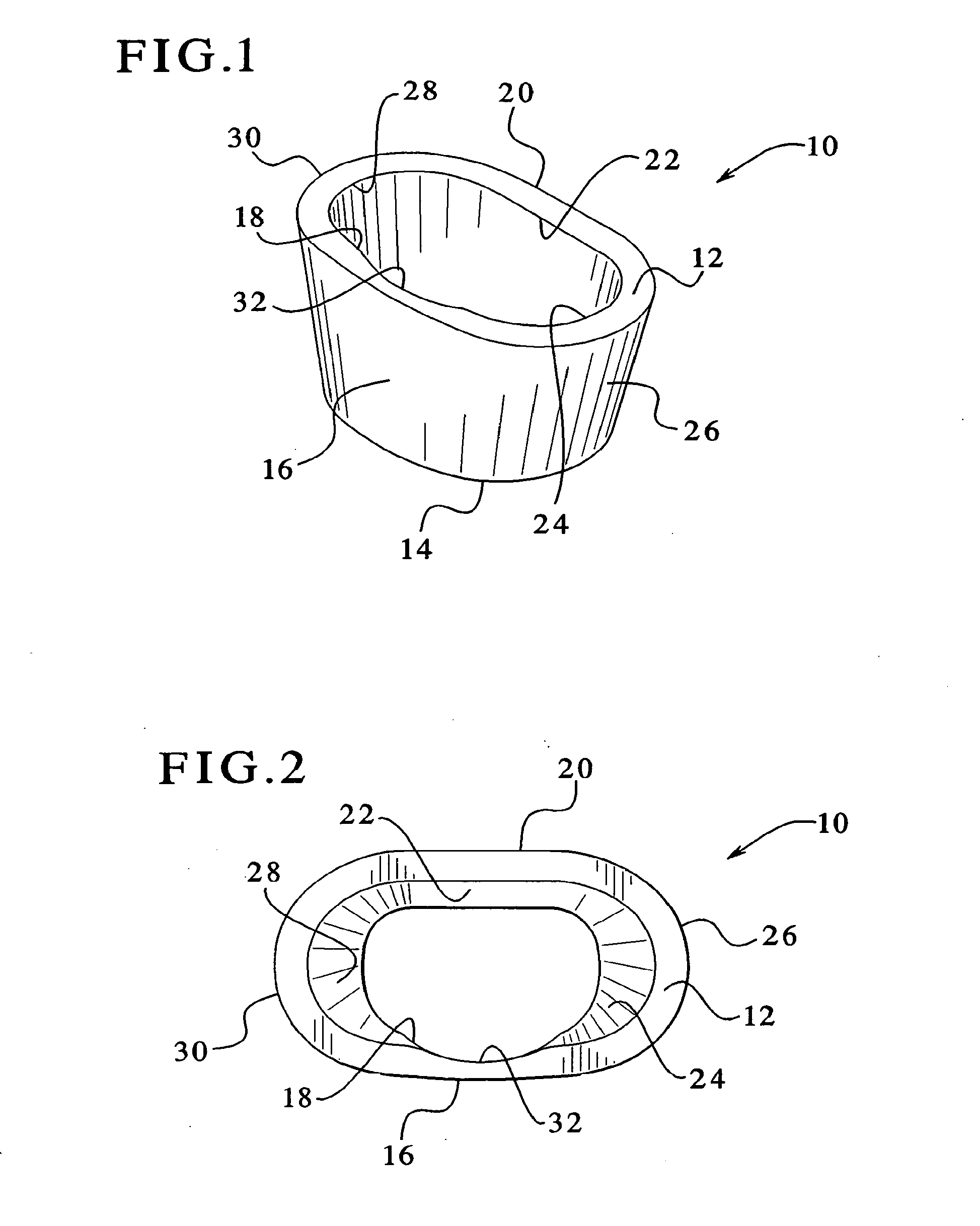
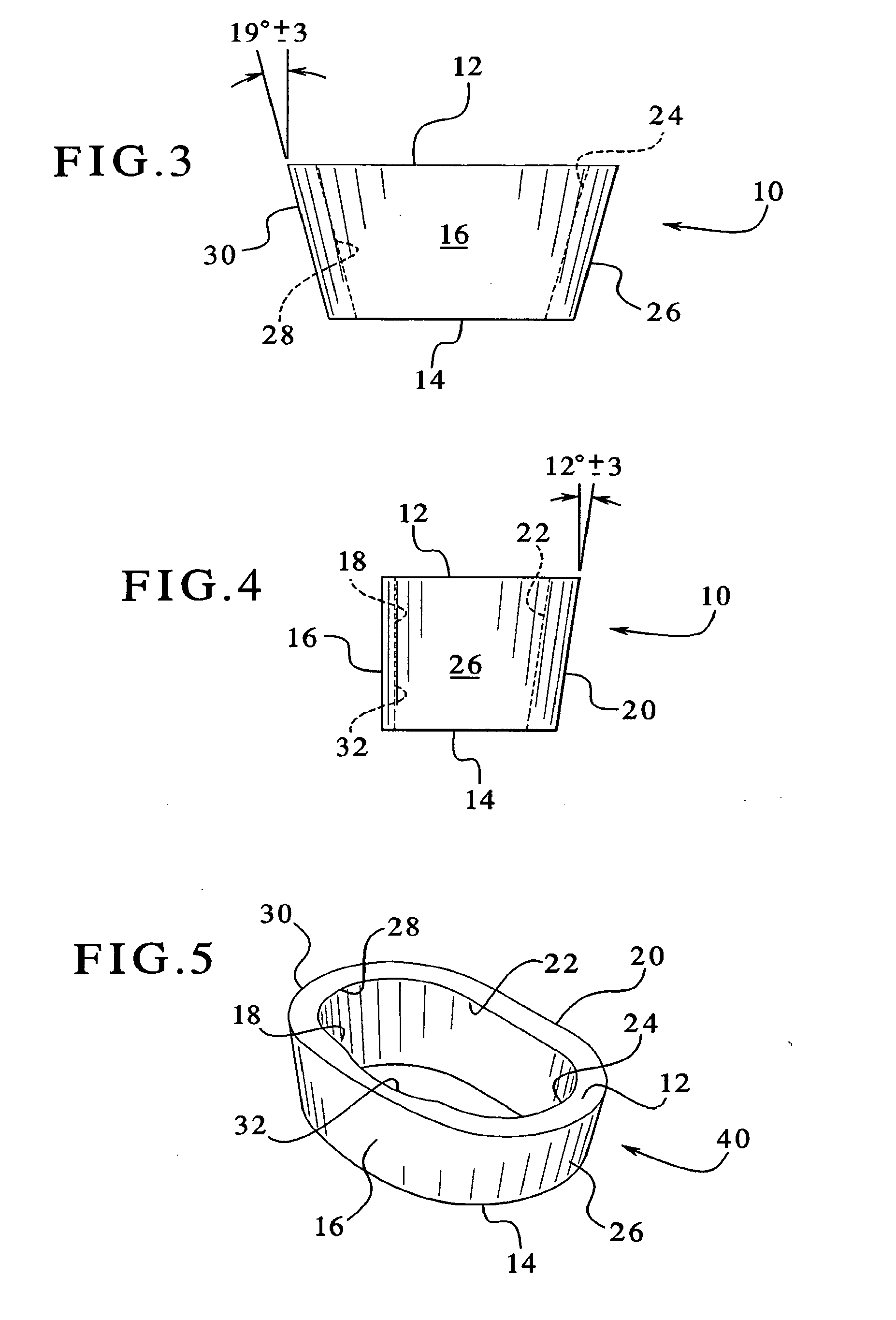
[0042]Referring to FIGS. 1 through 4, the tibial augment of the present invention is shown. The tibial augment is preferably an annular member 10, and it is preferably made from a tantalum based porous material, such as Trabecular Metal™. Trabecular Meta1™ is desirable because it resembles bone and approximates the physical and mechanical properties of bone better than other materials. Use of such a metal enables increased bonding with the adjacent bone by allowing the bone to grow into its highly porous surface. The tibial augment may also be made of other materials, and it is preferably made of a material that facilitates bony ingrowth.

[0043]The tibial augment 10 is anatomically sized and shaped to fill an existing cavitary defect within the proximal human tibia or a cavity prepared in the proximal portion of a human tibia. In the preferred embodiment, a system of different stock sizes of augments would be available, as discussed more fully below, with different sizes being used f...

second embodiment

[0057]a stepped tibial augment is shown in FIG. 6B, as represented by tibial augment 60. In this embodiment, as in the FIG. 6A embodiment, distal surface 14a is located at a greater distance from the proximal surface 12 than distal surface 14b. The main difference between this embodiment and the FIG. 6A embodiment is the location of the transition surface 52. In this embodiment, the transition surface 52 is located closer to the outer lateral surface 26 than to the outer medial surface 30.

third embodiment

[0058]FIG. 6C shows a stepped tibial augment 70. In this embodiment, as in the embodiments of FIGS. 6A and 6B, distal surface 14a is located at a greater distance from the proximal surface 12 than distal surface 14b. The main difference between this embodiment and the other two embodiments is the location of the transition surface 52. In this embodiment, the transition surface 52 is located closer to the outer medial surface 30 than to the outer lateral surface 26.

[0059]The embodiments of FIGS. 6A through 6C are especially useful where to there has been uneven tibial decay, i.e., where there is more decay on either the lateral side or the medial side than on the other side. By using one of the stepped tibial augments shown in FIGS. 6A through 6C, more healthy bone, if it exists on one side or the other, can be preserved, and mostly only defective bone will end up being removed when forming a stepped cavity to implant the tibial augment. In other words, the base of the cavity into wh...


PUM


Abstract

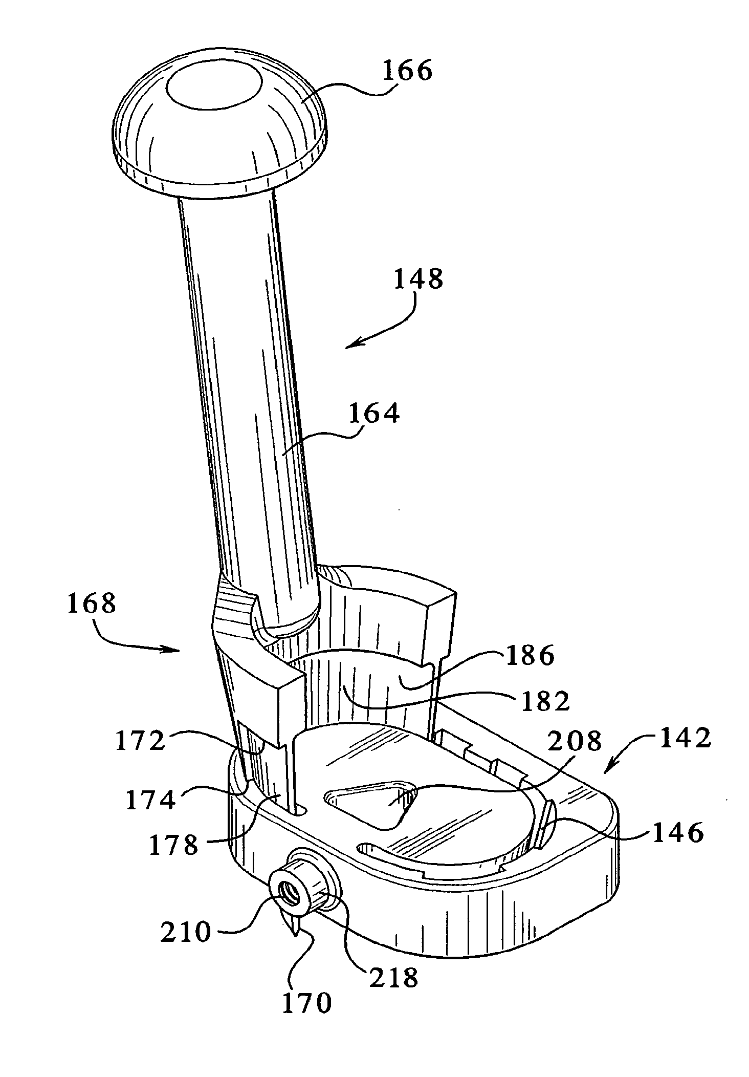
A tibial augment for use with a knee joint prosthesis, composed of annular members of different stock sizes, each size being configured to fit within a cavity formed in a human tibia. The augment may include a stepped distal surface. A provisional (temporary) tibial augment used to ensure a proper fit for the permanent augment is also provided. The provisional may include grooves configured to cooperate with a set of ribs on a tong-like holder used for removing the provisional from the cavity. A pusher for use implanting the tibial augment is also provided. In addition, a system for creating a cavity in a human tibia is also described. The system preferably includes a guide with a slot therein and a set of osteotomes that are inserted within different portions of the slot. Methods for using the tools and / or implanting the prosthetic devices discussed above are also described.

Description

[0001]This application is a continuation-in-part of prior application Ser. No. 10 / 225,774, filed Aug. 22, 2002, which claims the benefit of Provisional Application No. 60 / 315,148, filed Aug. 27, 2001, both of which are hereby incorporated by reference.[0002]The present invention relates generally to a bone augmenting member used to reinforce damaged bone, and more particularly to an augment for the proximal portion of a human tibia, where the augment is intended to be implanted in the proximal portion of the tibia, just slightly below the tibial portion of a knee joint prosthesis. The present invention also relates to the tool used for implanting the tibial augment, and the tools used for making the cavity in the bone to receive the augment. In addition, the invention also relates to a provisional augment used temporarily to ensure that the permanent augment will be seated within the bone correctly, as well as to a holder used for holding, inserting and removing the provisional augm...

Claims


Application Information

Patent Timeline
IPC IPC(8): A61F2/38A61B17/16A61B17/17A61B17/88A61B19/00A61F2/00A61F2/30A61F2/46
CPCA61B17/1604A61F2002/4628A61B17/1735A61B17/1764A61B2019/304A61F2/30734A61F2/30942A61F2/389A61F2/461A61F2/4684A61F2002/30209A61F2002/30217A61F2002/30324A61F2002/30326A61F2002/30616A61F2002/30708A61F2002/30736A61F2230/0067A61F2250/0036A61F2250/0037A61F2250/0084A61F2310/00131A61B17/1675A61B2090/034
Inventor BLAYLOCK, JEFFCOOK, MICHAELDONKERS, RONDYKEMA, SCOTTJONES, DAVIDMEYERS, JOHNVANKOSKI, STEPHENHANSSEN, ARLEN D.LEWALLEN, DAVID G.
Owner ZIMMER INC
Learn More