
Probability Distribution Function Mapping Method

a probability distribution and function mapping technology, applied in the field of probability distribution function mapping, can solve the problems of computational complexity, computational cost, and difficulty in getting accura

Inactive Publication Date: 2011-01-13
NORTHROP GRUMMAN SYST CORP
View PDF12 Cites 14 Cited by
  • Summary
  • Abstract
  • Description
  • Claims
  • Application Information

AI Technical Summary

Problems solved by technology

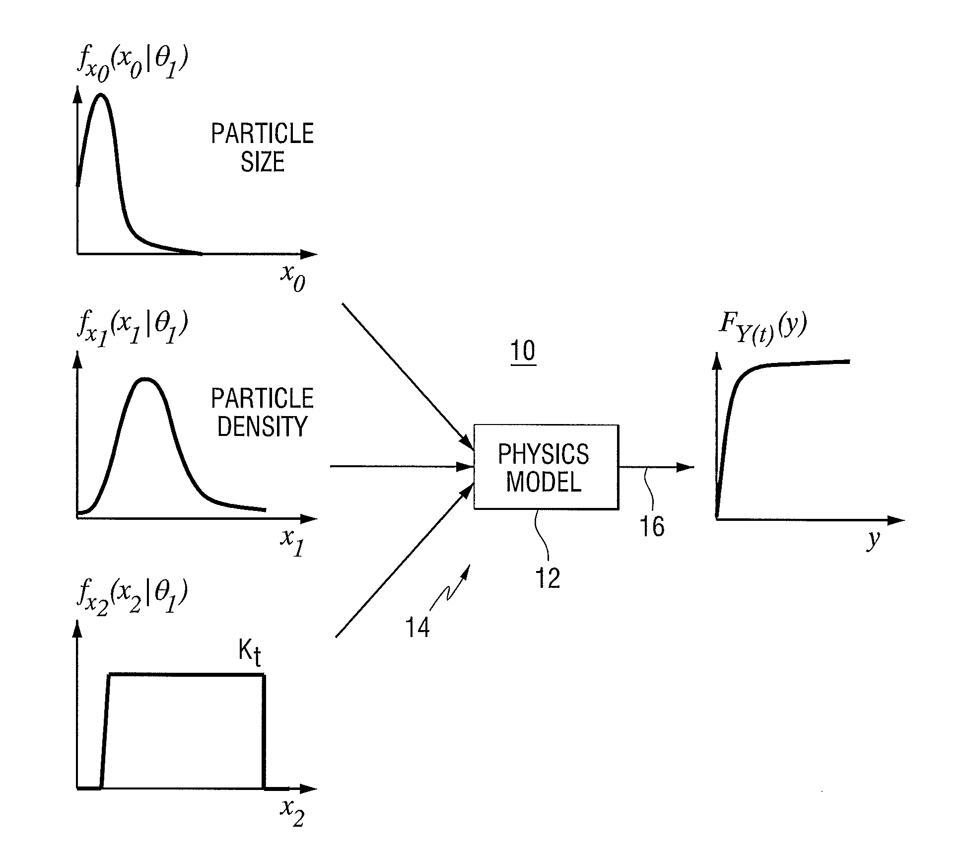
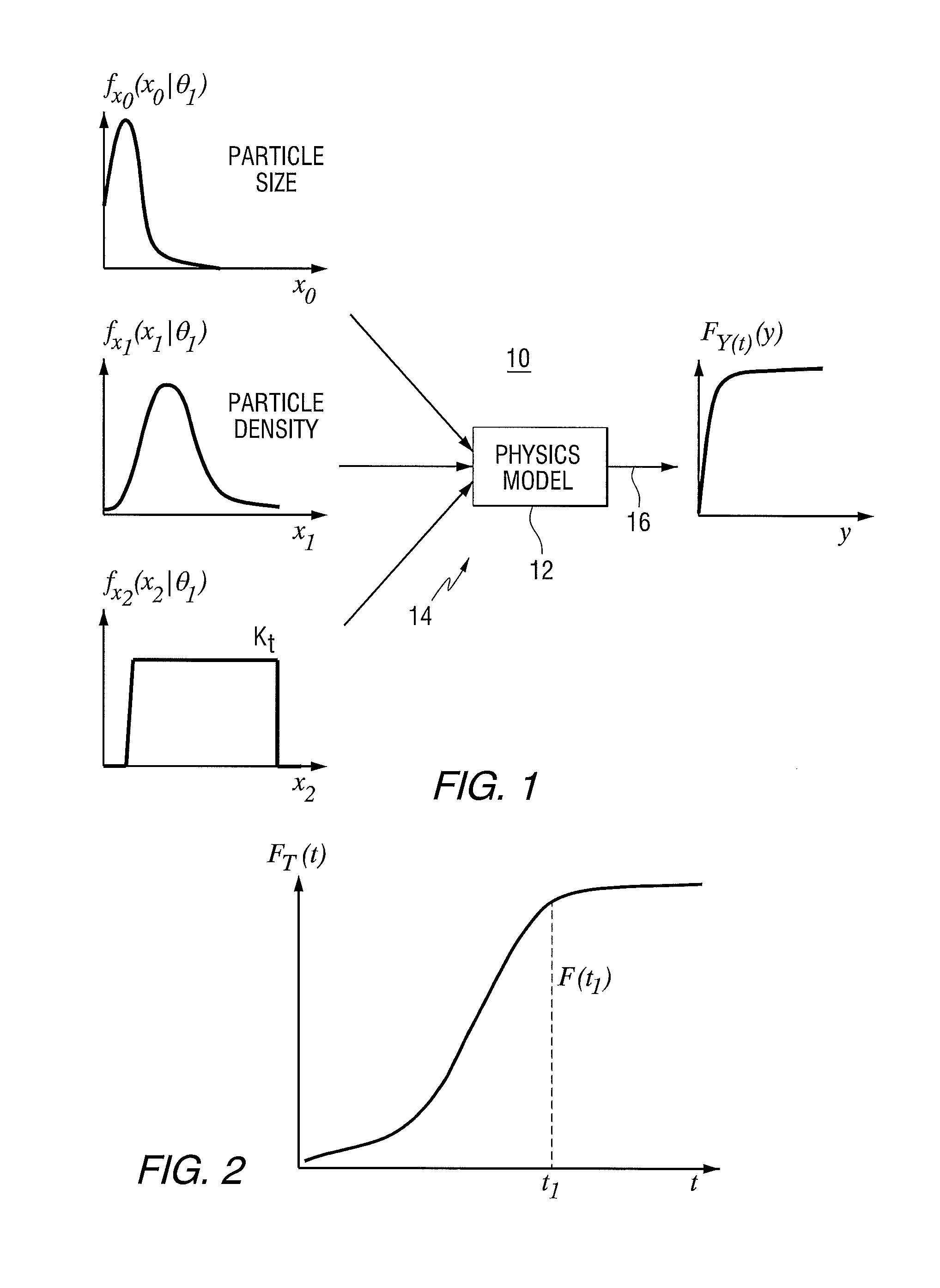
Physics models can be computationally complex, requiring a large number of input variables to conduct an accurate analysis of a system (FIG. 1).
However, it can be computationally expensive, and it is very difficult to get accurate results in the tails of the distribution due to the fact that the random samples occur in the tails infrequently due to the low probability of getting a value there.

Method used


Image

  • Probability Distribution Function Mapping Method
  • Probability Distribution Function Mapping Method
  • Probability Distribution Function Mapping Method

Examples


Embodiment Construction

[0018]In one aspect, this invention provides an exact representation of the output distribution for a stochastic process in terms of an input probability distribution and a mapping function (which can be defined by a physics model) relating the output to the input. For the purposes of this description, a mapping function is described by an equation or procedure that relates the output of a physics model with its inputs. An example physics model is a software application that calculates the crack (defect) length as a function of time given inputs of an initial crack size, material parameters, and loads.

[0019]FIG. 1 is a schematic diagram of a system 10 that can be used to implement an embodiment of the invention. The system includes a processor 12 that includes one or more inputs 14 for receiving input data, which can be represented by one or more random variables, and an output 16 for delivering a computed result. The processor implements a physics model to calculated output values....


PUM


Abstract

A method includes: receiving a plurality of values of an input variable representative of a physical characteristic of a component or system, using a physics model to produce an estimate of an output for each of the input values, mapping the output estimates to the input values to produce an output probability density or cumulative distribution function for the physical characteristic at a future time, and outputting the probability density or cumulative distribution function. An apparatus that implements the method is also provided.

Description

STATEMENT OF GOVERNMENT INTEREST[0001]This invention was made under Contract No. DARPA HR001-04-C-003. The United States Government has rights in this invention under the contract.FIELD OF THE INVENTION[0002]This invention relates to methods and apparatus for determining probability distribution functions and / or cumulative probability distributions.BACKGROUND OF THE INVENTION[0003]Physics-based probabilistic reliability / risk analysis can be used to predict the probabilities of component failure and to schedule maintenance of complex systems. A physics-based analysis uses a physics model to simulate the behavior of systems and components of such systems. Physics models can be computationally complex, requiring a large number of input variables to conduct an accurate analysis of a system (FIG. 1). The prediction of fatigue failure typically involves a model such as FASTRAN (commercially available software) where the size of a crack at some time t1 in the future, is a function of the i...

Claims


Application Information

Patent Timeline
Patent Type & Authority Applications(United States)
IPC IPC(8): G06F17/10
CPCG06F17/18
Inventor HOITSMA, DAVID H.ENGEL, STEPHEN J.
Owner NORTHROP GRUMMAN SYST CORP
Learn More