Portable ultrasonic diagnostic imaging system with docking station

A diagnostic imaging and ultrasound technology, which is applied in the directions of acoustic wave diagnosis, infrasonic wave diagnosis, ultrasonic/sonic wave/infrasonic wave diagnosis, etc.

Inactive Publication Date: 2008-04-16
KONINKLIJKE PHILIPS ELECTRONICS NV
View PDF9 Cites 21 Cited by
  • Summary
  • Abstract
  • Description
  • Claims
  • Application Information

AI Technical Summary

Problems solved by technology

However, this method still requires the physician to manipulate the small controls ...

Method used


Image

  • Portable ultrasonic diagnostic imaging system with docking station
  • Portable ultrasonic diagnostic imaging system with docking station
  • Portable ultrasonic diagnostic imaging system with docking station

Examples


Embodiment Construction

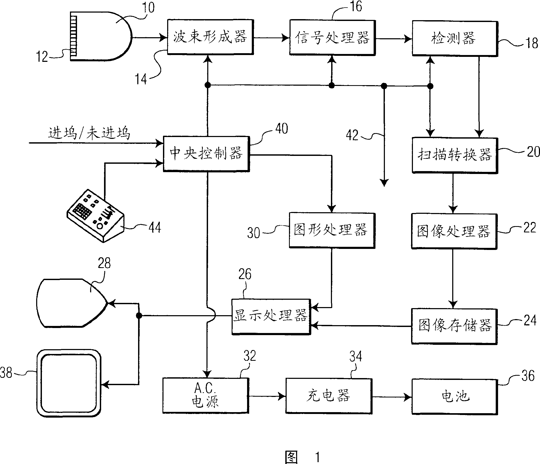
[0014] Referring first to Figure 1, there is shown in block diagram form an ultrasonic diagnostic imaging system constructed in accordance with the principles of the present invention. The ultrasonic probe 10 transmits and receives ultrasonic waves from piezoelectric elements in an array of transducer elements 12 . For imaging planar regions of the body, one-dimensional (1-D) element arrays can be used, while for imaging volumetric regions of the body, two-dimensional (2-D) element arrays can be used to direct and focused ultrasound beams. A transmit beamformer excites elements in the array to transmit ultrasound waves into the subject. The signals generated in response to the reception of ultrasound waves are coupled to a receive beamformer 14 . A beamformer delays and combines the signals from the individual transducer elements to form correlated beamformed echo signals. When the probe includes a 2-D array for 3D imaging, it may also include a microbeamformer, as describe...


PUM


Abstract

An ultrasonic diagnostic imaging system is described which is operable in the docked mode or in the portable mode. In the docked mode a portable ultrasound system (60) is docked with a docking station (50) . The portable ultrasound system (60) is controlled by hard key controls on a control panel of the docking station (50) and ultrasound images are displayed on a docking station display (28) . In the portable mode the portable ultrasound system is operated separate from the docking station (50) . Functions of a plurality of the hard keys of the control panel (44) are mapped to graphically displayed soft keys displayed on a flat panel display of the portable ultrasound system. The ultrasound system is controlled by clicking on these displayed soft keys or touching the displayed soft keys when the flat panel display is a touchscreen display.

Description

technical field [0001] The present invention relates to portable ultrasonic diagnostic imaging systems, and more particularly to portable ultrasonic systems that operate with a cart-like docking station Background technique [0002] As semiconductor devices become more miniaturized and have increasing functionality, it is possible to produce ultrasonic imaging devices that are smaller than before. This size reduction was first made possible by the personal computer (PC), which provided significant processing power in a desktop unit. US Patent 6,063,030 (Vara et al.) shows one of the earliest efforts to use a PC as the core of a desktop ultrasound system, and shows how one of the limitations of PC-based ultrasound systems is handled. Conventional cart-borne ultrasound systems have control panels and displays commonly referred to as user interfaces, which have a number of hardware and software controls specifically designed for the operation of the ultrasound system. However...

Claims


Application Information

Patent Timeline
IPC IPC(8): G01S15/89A61B8/00
CPCA61B8/00A61B8/4433A61B8/4405A61B8/08G01S15/899G01S7/52082G01S7/52079A61B8/546A61B8/467A61B8/4427G01S7/52074G01S7/52084A61B8/488A61B2560/0456A61B8/462A61B8/465A61B8/466
Inventor M·D·波兰德
Owner KONINKLIJKE PHILIPS ELECTRONICS NV
Why Eureka
Try Eureka