Automatic machine for punching and cutting wheel rims

a cutting wheel and automatic technology, applied in shearing machines, shearing control devices, shearing apparatus, etc., can solve the problems of increased machine cost and more difficult operation, and achieve the effect of accurate measuremen

Inactive Publication Date: 2011-01-20
ACTIVOS IND MADAMA SL
View PDF6 Cites 9 Cited by
  • Summary
  • Abstract
  • Description
  • Claims
  • Application Information

AI Technical Summary

Benefits of technology

[0019]The longitudinal sheet rests on a series of idler rollers, while is being dragged by using friction rollers driven by servo motor, and accurately measured by using an encoder.

Problems solved by technology

The inclusion of power units for each operation involves a greater complexity of the machine, as well as larger dimensions, which raise the cost of said machine and also mean a more difficult operation with the inclusion of a larger number of units and pieces.

Method used


Image

  • Automatic machine for punching and cutting wheel rims
  • Automatic machine for punching and cutting wheel rims
  • Automatic machine for punching and cutting wheel rims

Examples


Embodiment Construction

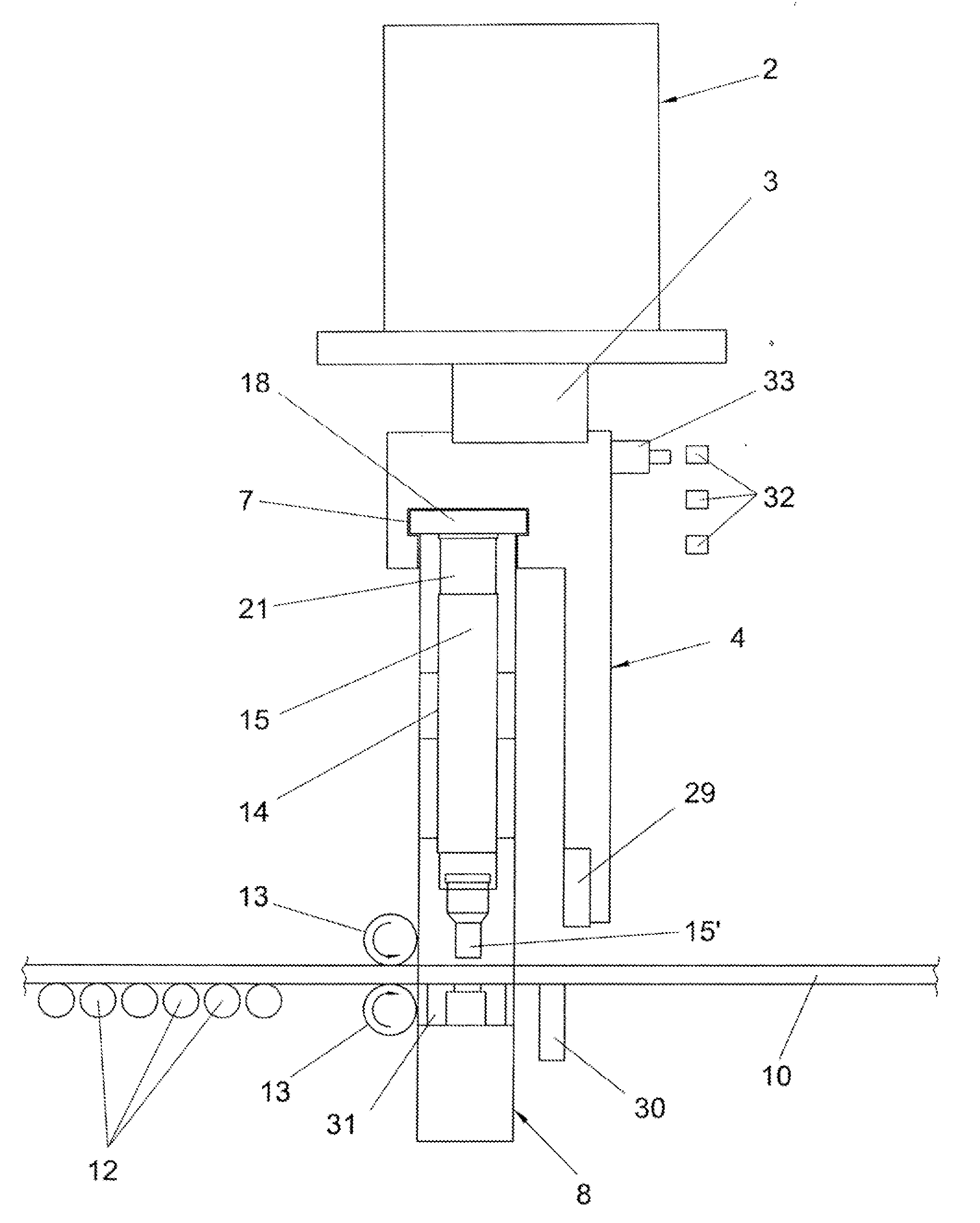
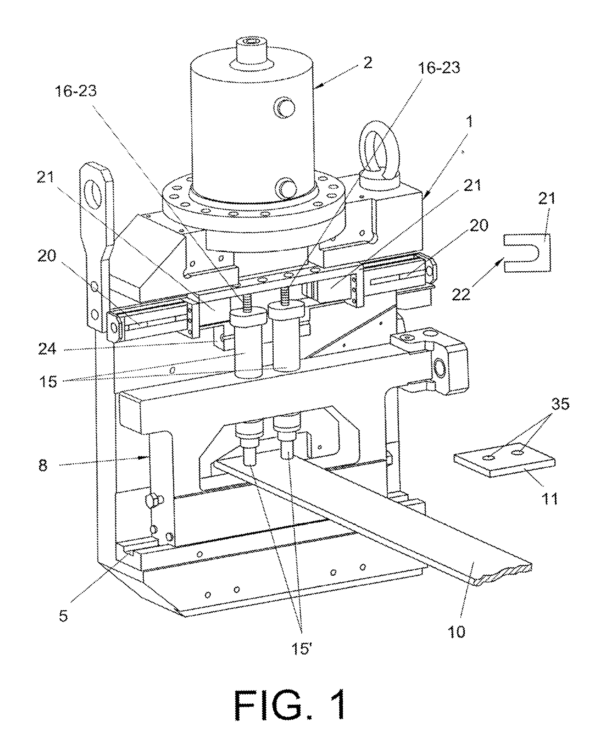
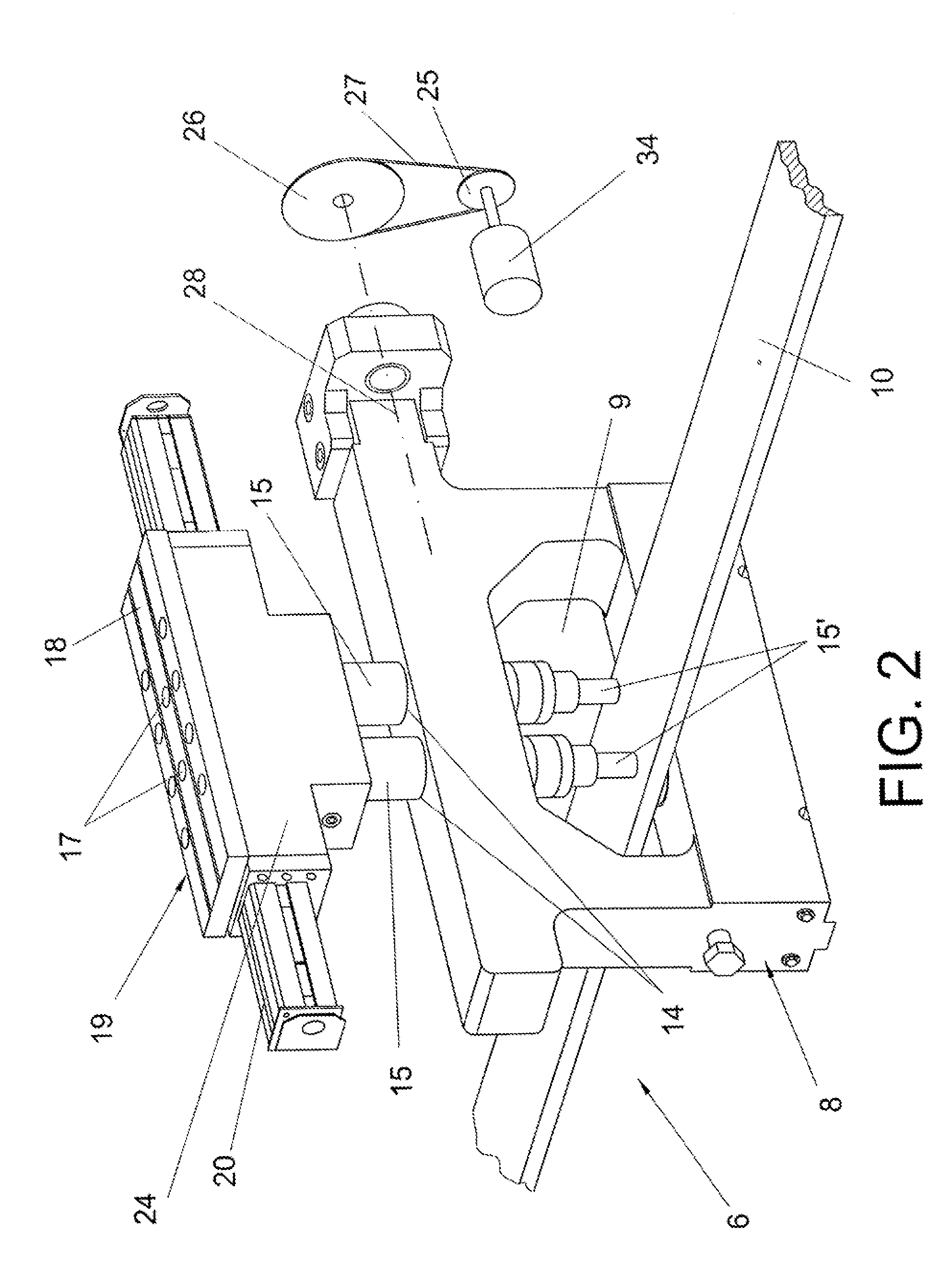
[0005]In order to achieve the objects and avoid the drawbacks mentioned in the preceding paragraphs, the invention proposes an automatic machine for punching and cutting wheel rims characterized in that it includes a single power unit, such as an oleohydraulic cylinder, for example, to perform the punching operation and the cutting operation, so that both are performed during the movement in a direction of the cylinder shaft, said movement being in a downward vertical direction.

[0006]The oleohydraulic cylinder acts in turn on a characteristic punching device and a characteristic cutting device both associated with each other, forming all the essence of the machine assembly of the invention.

[0007]The machine includes a sturdy frame, at the top of which the oleohydraulic cylinder is secured, a cutter-holding carriage that forms part of the cutting device being vertically guided on such frame, so that as the shaft moves out, it brings with it the cutter-holding carriage for cutting an ...


PUM

PropertyMeasurementUnit
transversal movementaaaaaaaaaa
sizeaaaaaaaaaa
vertical movementaaaaaaaaaa

Abstract

Machine for punching holes through a longitudinal sheet or wheel rim passing in a horizontal direction, using punches, and also for cutting said sheet to obtain sheet portions or pieces. The machine is characterized in that the punching and cutting operations are performed by a single power unit, such as an oleohydraulic cylinder (2) secured to a frame and positioned at the top in a vertical direction. The shaft of said cylinder is connected to a cutter-holding carriage (4) which, as it moves downwards to cut the sheet (10), brings with it an upper support means (19) that forms part of a punching device (6), the punches of which are guided on a lower front carriage (8) that also forms part of the punching device (6).

Description

OBJECT OF THE INVENTION[0001]The present invention, as this specification states in its title, relates to an automatic machine for punching and cutting wheel rims, essence of which is focused in that the punching and cutting operations are performed by a single power unit, preferably using an oleohydraulic cylinder, so that during the movement in a direction of its shaft both punching and cutting operations are performed, all this through an automatic process.[0002]This way the machine is kept compact and small in size, what lowers the cost of the mentioned machine and also results in a better utilization of raw material from which the different pieces are obtained.BACKGROUND OF THE INVENTION[0003]Currently, punching and cutting operations for obtaining pieces are performed through machines that include power units, such as oleohydraulic cylinders. These punching and cutting operations are performed separately, i.e. the punching is performed by a power unit and the cutting by anothe...

Claims


Application Information

Patent Timeline
Patent Type & Authority Applications(United States)
IPC IPC(8): B26D9/00
CPCB21D28/26B23D15/14B26D9/00B23D36/0091B23D31/00Y10T83/822Y10T83/8828Y10T83/8858B21D28/243B23D15/12B26F1/04
Inventor BARANDIARAN ECHEGUIA, JUAN IGNACIO
Owner ACTIVOS IND MADAMA SL
Why Eureka
Try Eureka