Heat Exchanger and Method for Making

Active Publication Date: 2011-01-20
LOCKHEED MARTIN CORP
View PDF22 Cites 35 Cited by
  • Summary
  • Abstract
  • Description
  • Claims
  • Application Information

AI Technical Summary

Benefits of technology

[0014]Like the prior-art, the fins are joined to the plates using a brazing process. In contrast to the prior-art, the present invention provides seals that fluidically isolate the brazed joints from the seawater. These seals are formed at each end of the core by joining the plates and a face sheet, disposed at that end, with a galvanic-corrosion-resistant joint. Because the brazed regions are not exposed to seawater, corrosion of the brazed joints is mitigated.
[0015]In some embodiments, the galvanic-corrosion-resistant joints are friction-stir welded, with the plates and the face

Problems solved by technology

OTEC systems have been shown to be technically viable, but the high capital cost of these systems has thwarted commercialization.
The heat exchangers are the second largest contributor to OTEC plant capital cost (the largest is the cost of the offshore moored vessel or platform).
Unfortunately, brazed joints are highly sus

Method used


Image

  • Heat Exchanger and Method for Making
  • Heat Exchanger and Method for Making
  • Heat Exchanger and Method for Making

Examples


Example

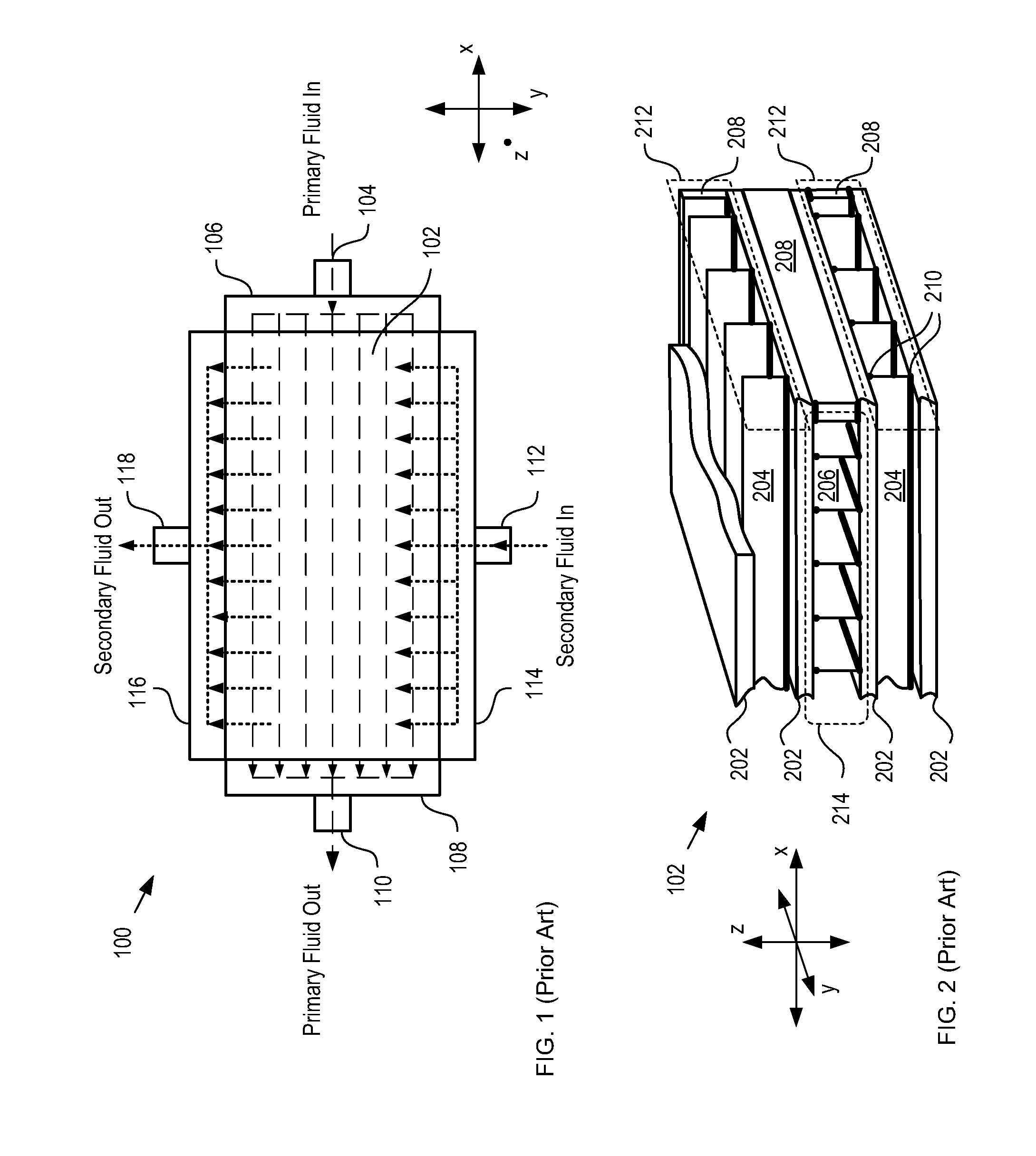
[0035]FIG. 1 depicts a schematic diagram of plate-fin heat exchanger in accordance with the prior art. Heat exchanger 100 comprises core 102, primary fluid inlet 104, manifolds 106, 108, 114, and 116, primary fluid outlet 110, secondary fluid inlet 112, and secondary fluid outlet 118.

[0036]In operation, heat exchanger 100 receives primary fluid at primary fluid inlet 104, which is fluidically coupled with manifold 106. Manifold 106 distributes the primary fluid to a plurality of flow channels, aligned with the x-direction, which are defined in core 102. After passing through core 102, the primary fluid is collected at manifold 108 and provided to primary fluid outlet 110.

[0037]In similar fashion, heat exchanger 100 receives secondary fluid at secondary fluid inlet 112, which is fluidically coupled with manifold 112. Manifold 112 distributes the secondary fluid to a plurality of flow channels, aligned with the y-direction, which are defined in core 102. After passing though core 102,...


PUM

PropertyMeasurementUnit
Lengthaaaaaaaaaa
Electrical resistanceaaaaaaaaaa

Abstract

A hybrid plate-fin heat exchanger for exchanging heat between a first fluid and a second fluid is disclosed. The hybrid plate-fin heat exchanger comprises a plurality of plates, each of which comprises channels for conveying the first fluid. Fins are brazed onto each plate, wherein the fins define a plurality of flow channels for the second fluid. The plates are joined to one another via friction-stir welding in such a way that the brazed regions are fluidically isolated from the first fluid during operation. As a result, the heat exchanger is suitable for use in applications that use a first fluid, such as seawater or geothermal fluid, which is corrosive for the brazed regions.

Description

CROSS REFERENCE TO RELATED APPLICATIONS[0001]This case claims priority of U.S. Provisional Patent Application Ser. No. 61 / 226,487, which was filed Jul. 17, 2009 (Attorney Docket: 711-285US), and which is incorporated herein by reference.[0002]If there are any contradictions or inconsistencies in language between this application and one or more of the cases that have been incorporated by reference that might affect the interpretation of the claims in this case, the claims in this case should be interpreted to be consistent with the language in this case.FIELD OF THE INVENTION[0003]The present invention relates to heat exchangers in general, and, more particularly, to heat exchangers for Ocean Thermal Energy Conversion systems.BACKGROUND OF THE INVENTION[0004]Ocean thermal energy conversion (“OTEC”) is a method for generating electricity based on the temperature difference that exists between deep and shallow waters of a large body of water, such as an ocean. An OTEC system utilizes ...

Claims


Application Information

Patent Timeline
IPC IPC(8): F28F3/08B21D53/02
CPCF28D7/1684F28D9/0062F28D9/0081F28F3/025F28F9/18Y10T29/4935F28F21/08F28F2275/04F28F2275/062Y02E10/34F28F2009/226F28F19/00Y02E10/30
Inventor LEVINGS, NATALIE B.NAGURNY, NICHOLAS J.ELLER, MICHAEL R.
Owner LOCKHEED MARTIN CORP
Why Eureka
Try Eureka