Fixed frequency dimming method and fixed frequency dimming circuit for light emitting module

a light-emitting module and fixed-frequency dimming technology, which is applied in the direction of instruments, light sources, electroluminescent light sources, etc., can solve the problems of reducing conversion efficiency, difficult protection design of electromagnetic interference (emi), and often affecting the conversion efficiency of dc/dc, so as to achieve constant oscillation frequency of hysteresis control circuit and fixed conversion efficiency

Active Publication Date: 2011-01-20
MACROBLOCK INC
View PDF3 Cites 4 Cited by
  • Summary
  • Abstract
  • Description
  • Claims
  • Application Information

AI Technical Summary

Benefits of technology

Subsequently, the controlled current source provides a variable voltage at the upper limit voltage end, so as to adjust an output level (that is, a driving current of the light emitting module), thereby changing the light emitting brightness of the light emitting module.
In conclusion, in the fixed frequency dimming method and the fixed frequency dimming circuit for a light emitting module according to the present invention, light emitting brightness of the light emitting module is controlled by a hysteresis control circuit. A voltage difference between an upper limit voltage and a lower limit voltage of a hysteresis width of

Problems solved by technology

However, when the oscillation frequency changes with the level of the output current, the protection design of electromagnetic interference (EMI) is relatively difficult.
Moreo

Method used


Image

  • Fixed frequency dimming method and fixed frequency dimming circuit for light emitting module
  • Fixed frequency dimming method and fixed frequency dimming circuit for light emitting module
  • Fixed frequency dimming method and fixed frequency dimming circuit for light emitting module

Examples


Embodiment Construction

In the present invention, a hysteresis control circuit is used to control light emitting brightness of a light emitting module. A voltage difference between an upper limit voltage and a lower limit voltage of a hysteresis width of the hysteresis control circuit is maintained at a fixed value, and a driving current flowing through the light emitting module is changed by changing the upper limit voltage or the lower limit voltage.

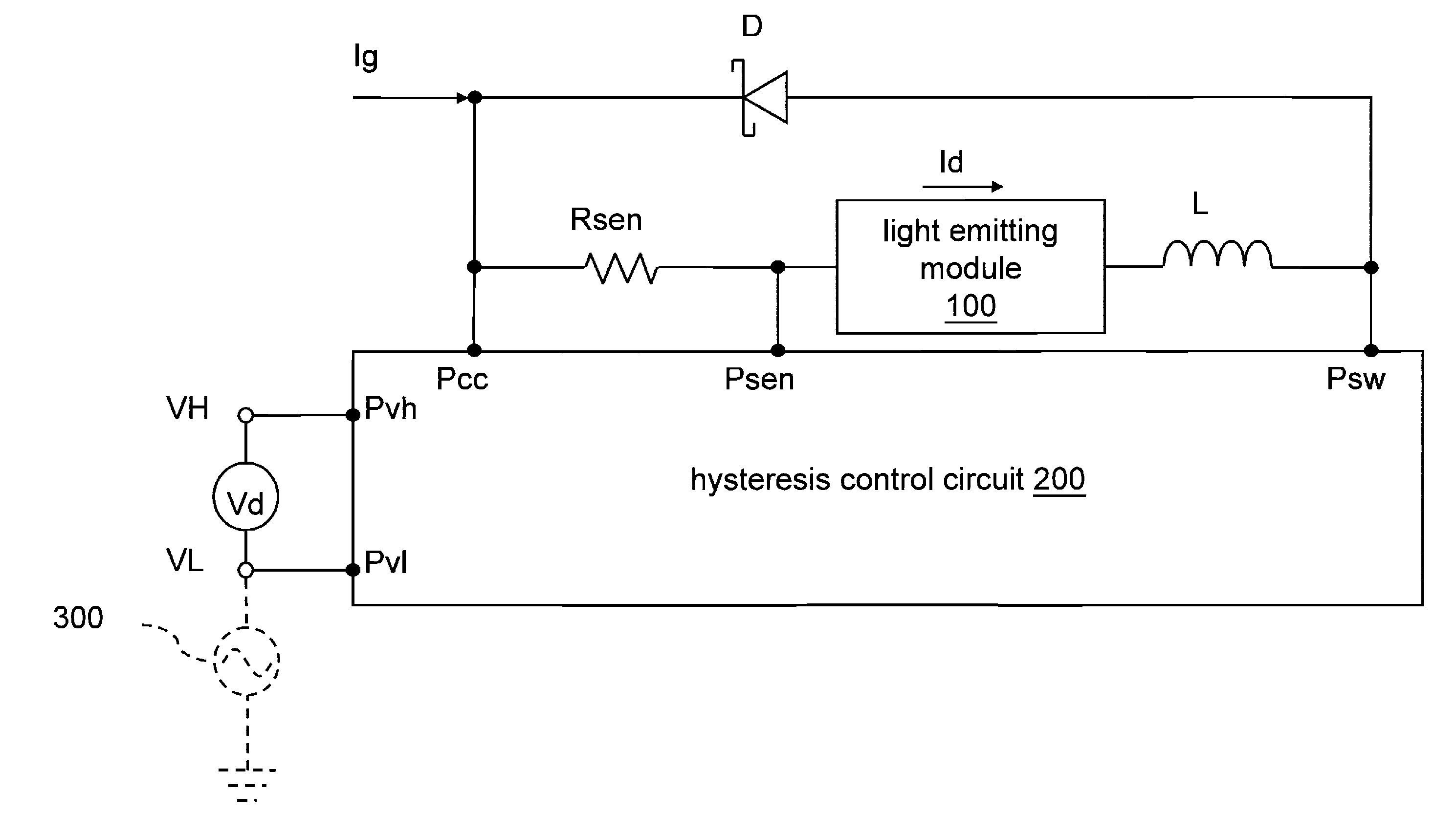
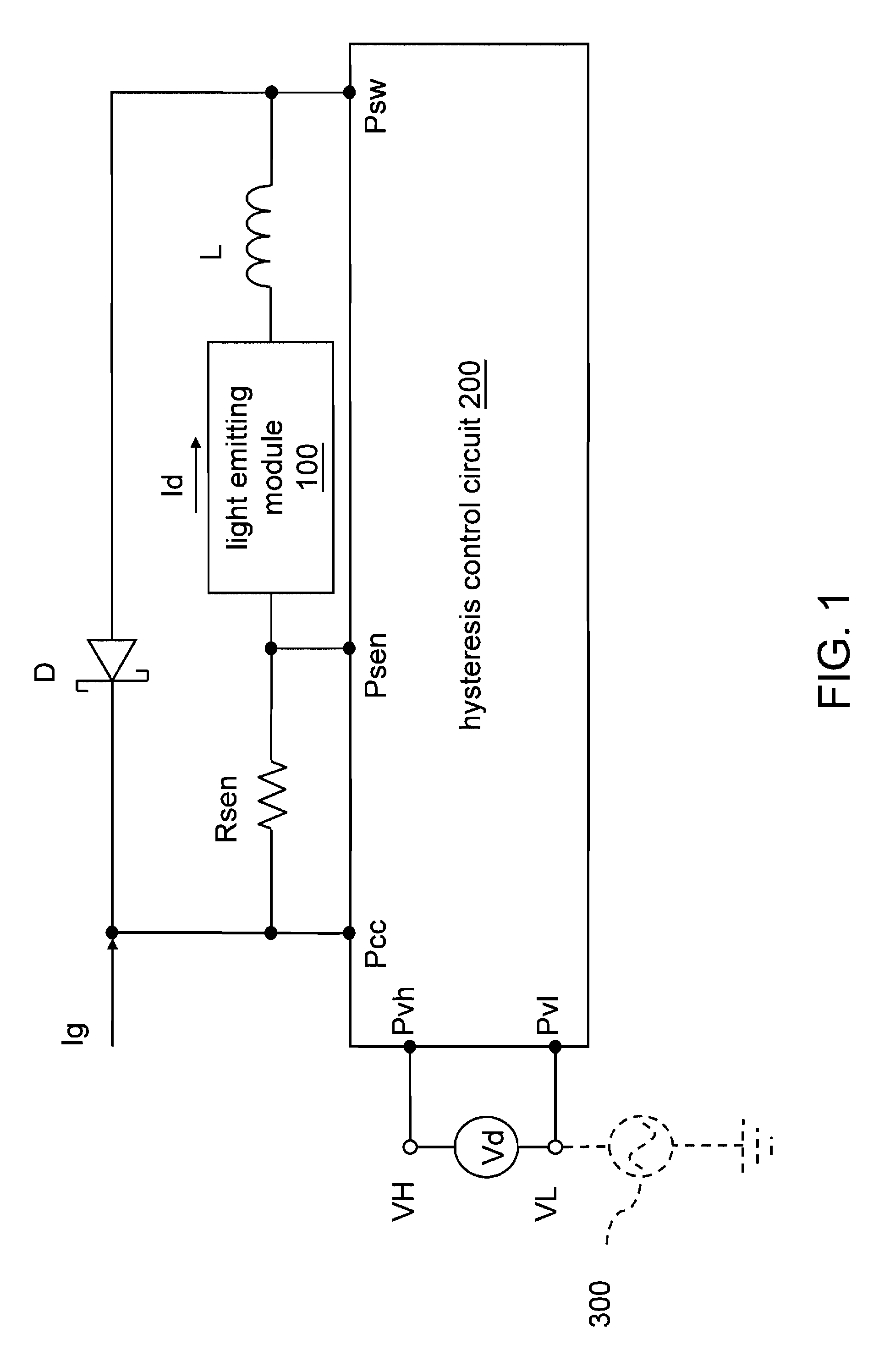
FIG. 1 shows a fixed frequency dimming circuit for a light emitting module according to an embodiment of the present invention. The “connections” in the embodiments below are electrical connections.

Referring to FIG. 1, the fixed frequency dimming circuit for a light emitting module comprises a hysteresis control circuit 200, an inductor component L, and an impedance component Rsen.

The hysteresis control circuit 200 has a voltage input end Pcc, a sensing end Psen, a switching end Psw, an upper limit voltage end Pvh, and a lower limit voltage end Pvl.

The upper ...


PUM


Abstract

A fixed frequency dimming method and fixed frequency dimming circuit for a light emitting module can control light emitting brightness of the light emitting module through a hysteresis control circuit. A voltage difference between an upper limit voltage and a lower limit voltage of a hysteresis width of the hysteresis control circuit is maintained at a fixed value, and a driving current flowing through the light emitting module is changed by changing the upper limit voltage or the lower limit voltage.

Description

CROSS-REFERENCE TO RELATED APPLICATIONSThis non-provisional application claims priority under 35 U.S.C. §119(a) on Patent Application No(s). 098123976 filed in Taiwan, R.O.C. on Jul. 15, 2009, the entire contents of which are hereby incorporated by reference.BACKGROUND1. Field of InventionThe present invention relates to a brightness adjusting method, and more particularly to a fixed frequency dimming method and a fixed frequency dimming circuit for a light emitting module.2. Related ArtIn recent years, the manufacturing technology of a light emitting diode (LED), one of semiconductor light emitting components, develops rapidly. In particular, since a blue LED is successfully developed, such that LEDs having three primary colors of light are all available, light of various wavelengths may be realized by combining the LEDs of three primary colors. Therefore, the application scope of the LEDs rapidly expands.As for operational characteristics, brightness of an LED changes with a curre...

Claims


Application Information

Patent Timeline
IPC IPC(8): H05B37/02
CPCH05B33/0815H05B45/3725
Inventor CHENG, CHIN CHUNG
Owner MACROBLOCK INC
Why Eureka
Try Eureka