Image display apparatus and image display method

Inactive Publication Date: 2011-01-20
KK TOSHIBA
View PDF10 Cites 15 Cited by
  • Summary
  • Abstract
  • Description
  • Claims
  • Application Information

AI Technical Summary

Benefits of technology

[0036]In the following, the configuration and operation of each unit are described in detail.
[0085]According to the image display apparatus relevant to the present embodiment, it is possible to make an image display with a wide dynamic range and low consumption power with fluctuations in luminance alleviated due to the averaging effect and the flickering thus suppressed.
[0086]An image display apparatus according to a second embodiment of the present invention is described with reference to drawings.
[0087]FIG. 14 shows a configuration of the image display apparatus according to the present embodiment. The image display apparatus according to the second embodiment is vastly different from the image display apparatus according to the first embodiment in that the light-emission intensity and the light-emission timing of each of a plurality of light sources constituting a backlight 44 are individually controllable by a backlight controlling unit 43. Further, the image display apparatus according to the present embodiment desirably has a luminance distribution calculating unit 47, a

Problems solved by technology

However, since spatial and temporal fluctuations in maximum value of the luminance of the image are drastic, fluctuations i

Method used


Image

  • Image display apparatus and image display method
  • Image display apparatus and image display method
  • Image display apparatus and image display method

Examples


first embodiment

[0033]An image display apparatus according to a first embodiment of the present invention is described with reference to drawings.

Configuration of Image Display Apparatus

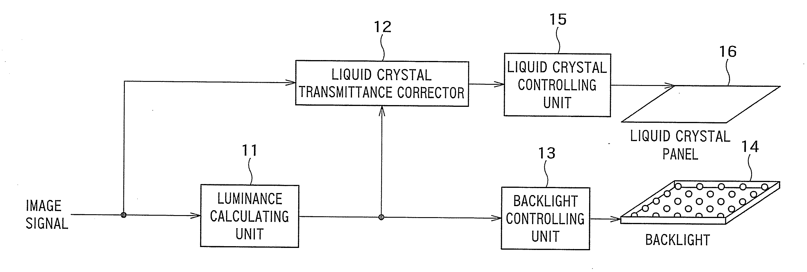
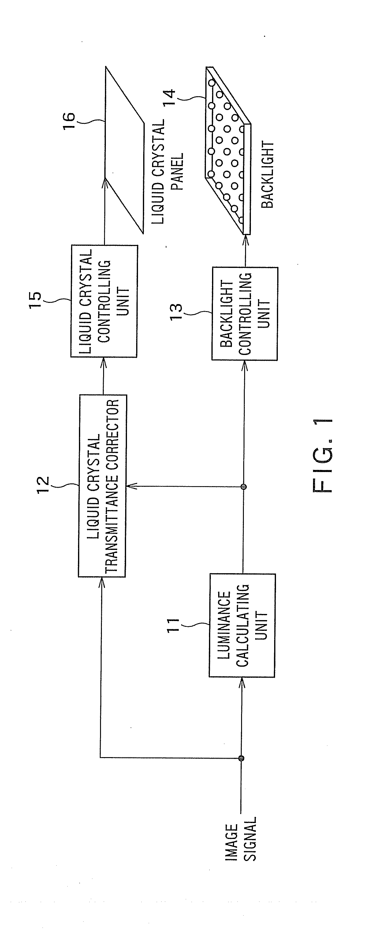
[0034]FIG. 1 shows a configuration of the image display apparatus according to the present embodiment. An image display apparatus according to the present embodiment includes a luminance calculating unit 11, a liquid crystal transmittance corrector 12, a backlight controlling unit 13, a backlight 14, a liquid crystal controlling unit 15, and a liquid crystal panel 16 where a plurality of pixels are arrayed in matrix form.

[0035]The luminance calculating unit 11 calculates a luminance modulation ratio of the backlight 14 which is suitable for display based upon an image signal of one frame. The liquid crystal transmittance corrector 12 corrects a luminance (light transmittance) of each pixel in the image signal based upon the calculated luminance modulation ratio (light-emission luminance) of the backlight 14, and out...

second embodiment

[0086]An image display apparatus according to a second embodiment of the present invention is described with reference to drawings.

Configuration of Image Display Apparatus

[0087]FIG. 14 shows a configuration of the image display apparatus according to the present embodiment. The image display apparatus according to the second embodiment is vastly different from the image display apparatus according to the first embodiment in that the light-emission intensity and the light-emission timing of each of a plurality of light sources constituting a backlight 44 are individually controllable by a backlight controlling unit 43. Further, the image display apparatus according to the present embodiment desirably has a luminance distribution calculating unit 47, and in the present embodiment, it is assumed that the apparatus has the luminance distribution calculating unit 47.

[0088]In the following, the configuration and operation of each unit are described in detail.

Backlight 44

[0089]The backligh...


PUM


Abstract

An image display apparatus includes: a backlight configured to emit light; a liquid crystal panel configured to modulate light emitted from the backlight to make an image display; a backlight luminance calculating unit configured to calculate a light-emission luminance of the backlight such that a center value of a luminance range displayable on the liquid crystal panel defined depending on the light-emission luminance of the backlight substantially agrees with a center value of luminances of pixels forming an input image; a backlight controlling unit configured to control light emission of the backlight so that the light from the backlight is emitted with the calculated light-emission luminance; a luminance correcting unit configured to correct the luminance of each pixel in the input image in accordance with the calculated light-emission luminance; and a liquid crystal controlling unit configured to control modulation of the liquid crystal panel based upon the corrected input image.

Description

TECHNICAL FIELD[0001]The present invention relates to an image display apparatus and an image display method.[0002]1. Background Art[0003]Conventionally, in a liquid crystal display apparatus, a luminance of a backlight has been controlled for purposes of expanding a display dynamic range, lowering consumption power, and the like.[0004]For example, in JP-A 2005-309338 (Kokai), a luminance of a backlight is controlled so that the maximum luminance in the input image can be displayed by calculating a modulation ratio of the luminance of the backlight from the maximum luminance value in an input image.[0005]However, since spatial and temporal fluctuations in maximum value of the luminance of the image are drastic, fluctuations in luminance of the backlight calculated based upon the maximum value are also drastic, leading to flickering of the display.[0006]2. Disclosure of the Invention[0007]According to an aspect of the present invention, there is provided with an image display apparat...

Claims


Application Information

Patent Timeline
IPC IPC(8): G09G3/36
CPCG09G3/3413G09G3/3648G09G2320/0673G09G2320/0276G09G2320/0646G09G5/06
Inventor NONAKA, RYOSUKEBABA, MASAHIROITOH, GOH
Owner KK TOSHIBA
Why Eureka
Try Eureka