Medical imaging method and system for providing a finite-element model

a medical imaging and finite element technology, applied in the field of medical imaging methods and systems for providing finite element models, can solve problems such as difficult simulations, and achieve the effect of reducing radiation doses

Inactive Publication Date: 2011-01-20
ECOLE NAT SUPERIEURE DARTS & METIERSENSAM
View PDF7 Cites 38 Cited by
  • Summary
  • Abstract
  • Description
  • Claims
  • Application Information

AI Technical Summary

Benefits of technology

[0013]In some embodiments, one might also use one or more of the features defined in the dependent cla...

Problems solved by technology

Such simulations are difficult: it is necessary to obtain a precise geometry of the bony structure, the...

Method used


Image

  • Medical imaging method and system for providing a finite-element model
  • Medical imaging method and system for providing a finite-element model
  • Medical imaging method and system for providing a finite-element model

Examples


Embodiment Construction

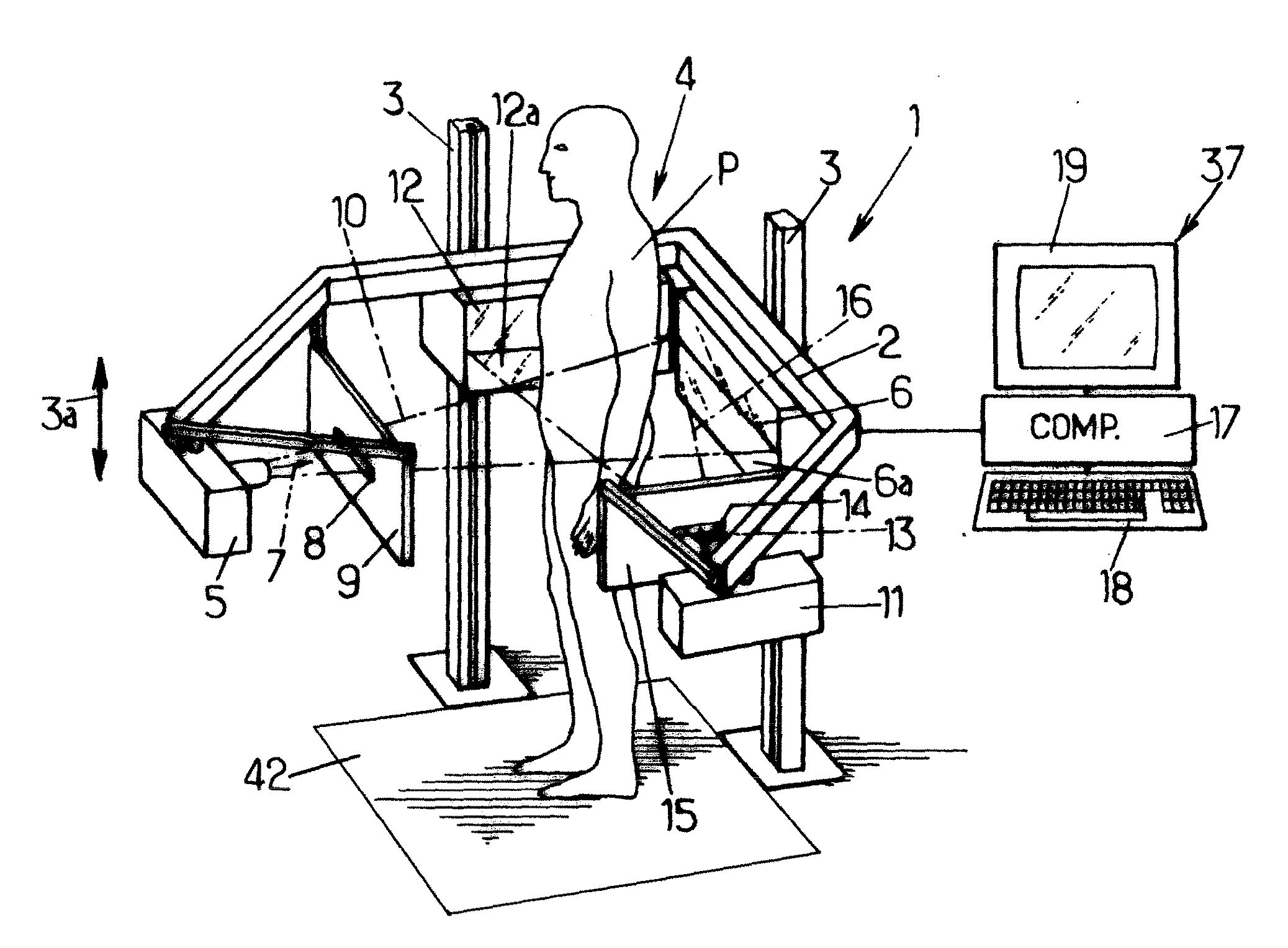
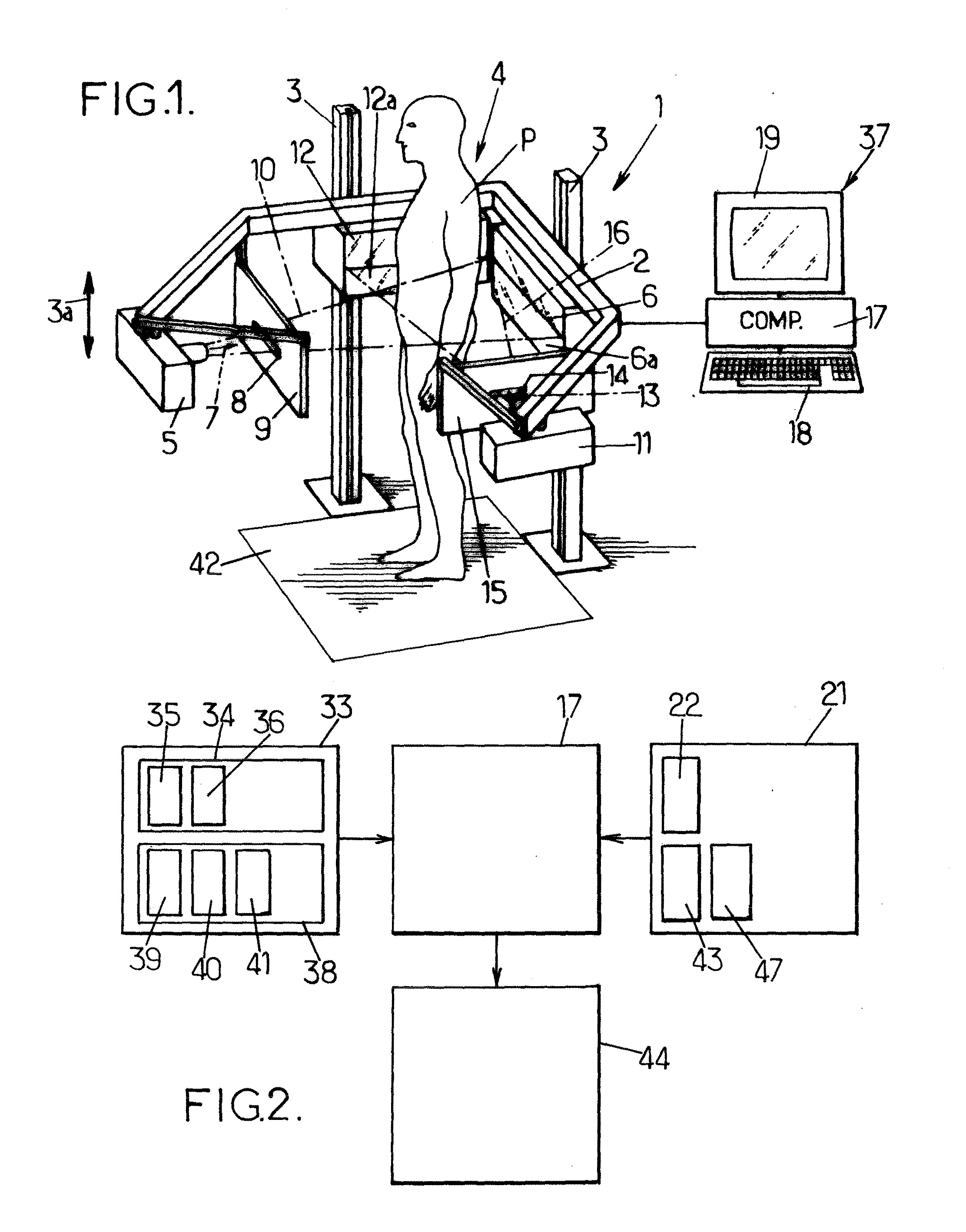
[0026]FIG. 1 shows a radiographic apparatus 1 for three-dimensional reconstruction, the apparatus comprising a moving frame 2 displaceable under motor drive along vertical guides 3 in both directions of translation 3a.

[0027]The frame surrounds a field of observation 4 in which a patient P may be placed in a given position, e.g. standing, for observing an osteo-articular structure of the patient when in the standing position, which may be relevant for patients suffering from postural imbalance for example.

[0028]The moving frame 2 carries a first radiological source 5 and a first detector 6 which is placed facing the source 5 beyond the field 4, and which comprises at least one horizontal line 6a of detector cells. By way of example, the detector 6 may be a gas detector responsive to low doses of radiation, e.g. as described in documents FR-A-2 749 402 or FR-A-2 754 068. Naturally, other types of detectors may optionally be used in the context of the present invention.

[0029]The radio...


PUM


Abstract

A method comprising: -providing acquisition data (34,38) of a patient, comprising acquisition data of a bone structure of the patient in a given position, providing a knowledge base (22,43,47), comprising data related to such bone structures, -determining a patient-specific position-specific finite-element model of the bone structure comprising: patient-specific three-dimensional geometry, patient-specific mechanical characteristics of the bone structure, and patient-specific position-specific mechanical load applied to the bone structure in the position.

Description

CROSS-REFERENCE[0001]The present application is the U.S. National Stage of PCT / IB2008 / 051807 filed Feb. 29, 2008, the entirety of which is incorporated herein by reference.FIELD OF THE INVENTION[0002]The instant invention relates to medical imaging methods and systems for providing a finite-element model.BACKGROUND OF THE INVENTION[0003]When it comes to mechanical structures, the advantages of the finite-element-method are well known. Recently, attempts were made to use this method to simulate the behaviour of body structures, in particular bony structures of a patient as a mechanical system. Such simulations are difficult: it is necessary to obtain a precise geometry of the bony structure, the mechanical properties of the internal body organs, and the applied loads (also called “boundary conditions”). An attempt to provide such a finite-element-model is described in U.S. Pat. No. 5,172,695. In this patent, the three-dimensional geometry is obtained using a conventional Computer Tom...

Claims


Application Information

Patent Timeline
IPC IPC(8): A61B5/05G06N5/00G06F19/00
CPCG06F19/3437G16H50/50G16H30/20
Inventor SKALLI, WAFAMITTON, DAVIDDUBOUSSET, JEANLAVASTE, FRANCOIS
Owner ECOLE NAT SUPERIEURE DARTS & METIERSENSAM
Why Eureka
Try Eureka