
Attitude control device

a technology of attitude control and gear control, which is applied in the direction of locomotives, instruments, transportation and packaging, etc., can solve the problems of generating gyro moment, affecting the motion of the vehicle body, and flywheels also having problems, so as to eliminate the detrimental influence of motion and simple structure

Active Publication Date: 2011-01-27
SUDA YOSHIHIRO
View PDF19 Cites 31 Cited by
  • Summary
  • Abstract
  • Description
  • Claims
  • Application Information

AI Technical Summary

Benefits of technology

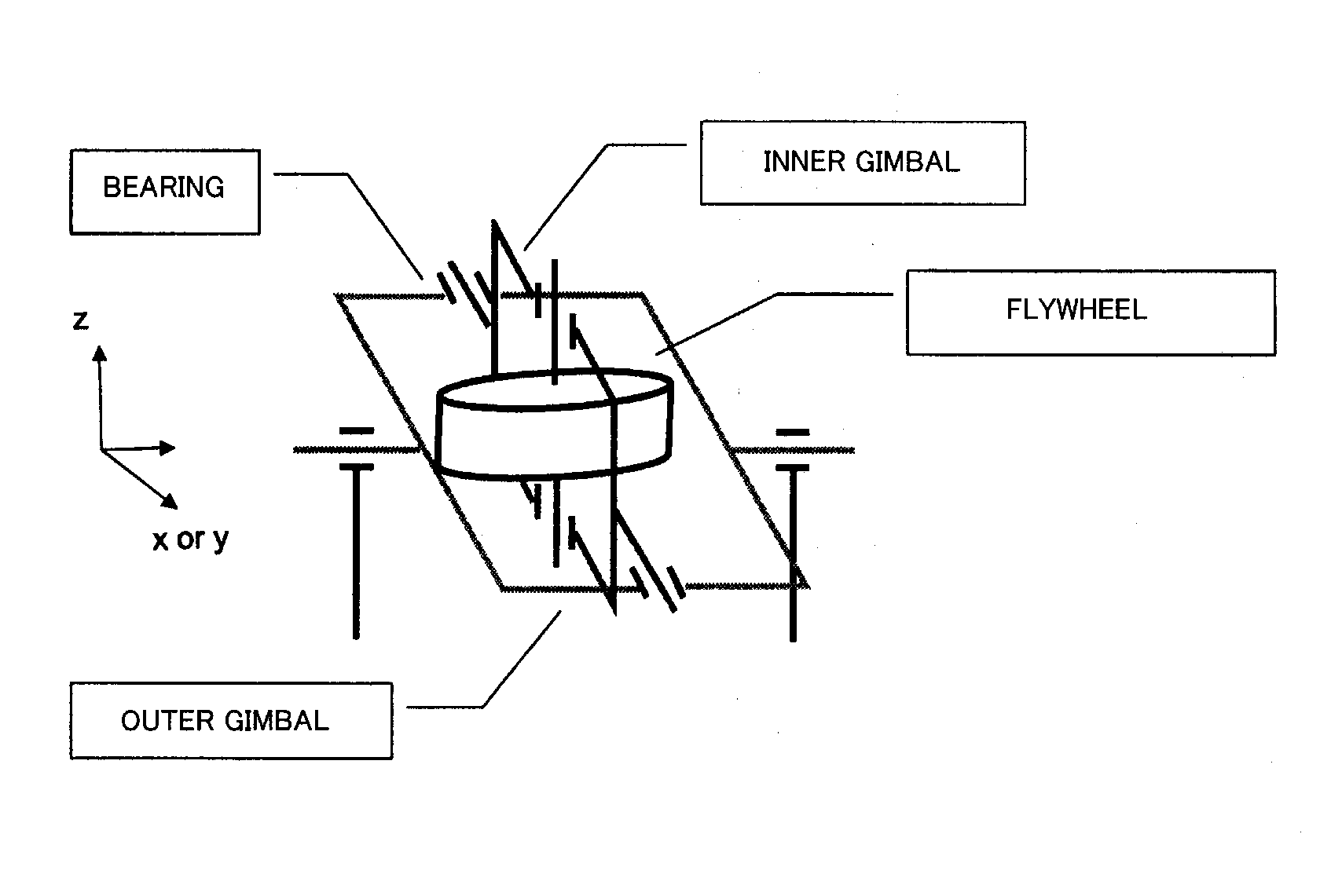
[0020]The flywheel of the present invention is capable of eliminating the detrimental influence on the motion of the vehicle due to having a support structure enabling free rotation about two orthogonal axes. The flywheel of the present invention also carries out rolling control of a vehicle by actively utilizing gyro moment generated by the flywheel constituting the energy storing device.
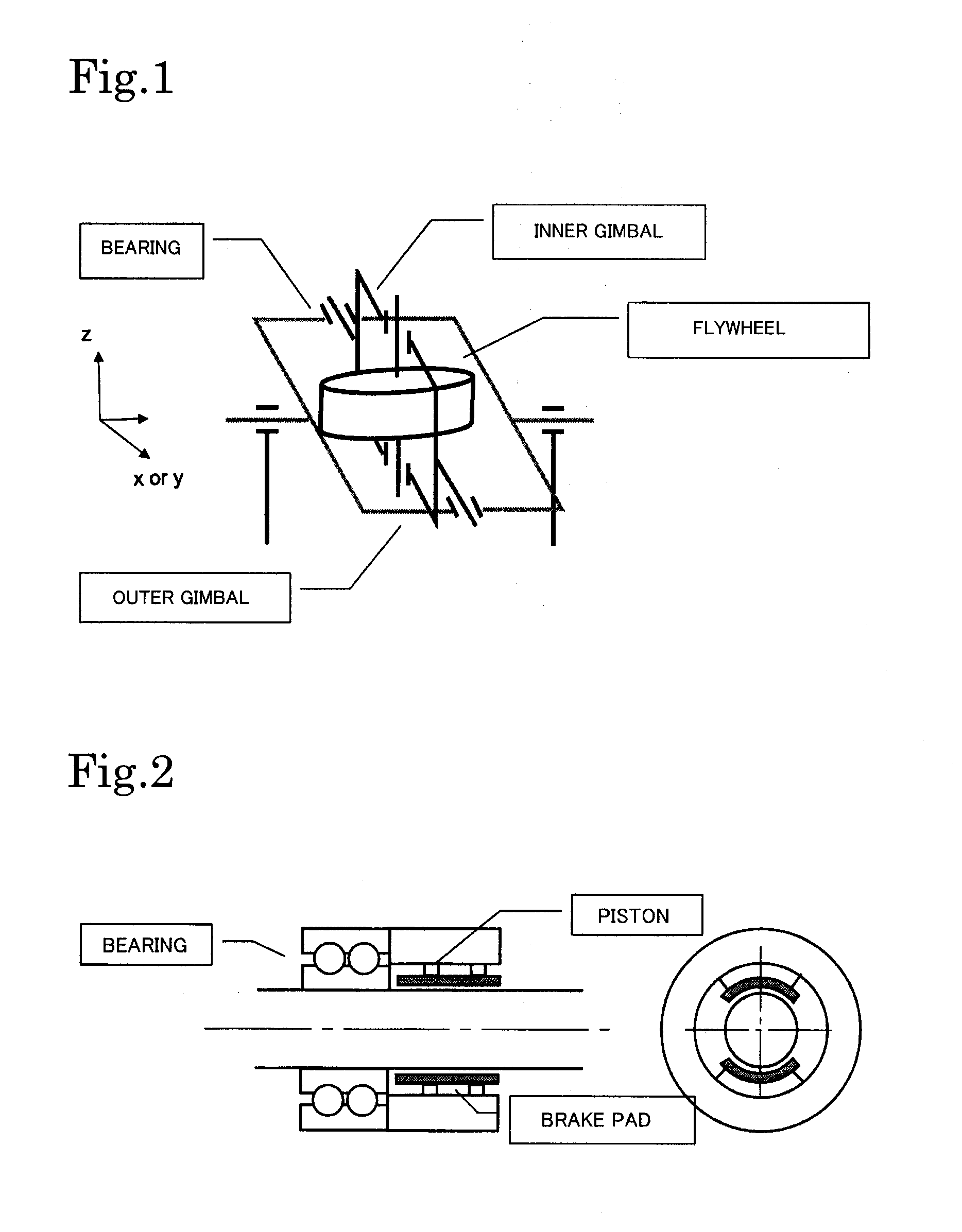
[0021]The flywheel is pivotally supported about mutually orthogonal first and second axes and is capable of carrying out rolling control of the vehicle using a simple structure as a result of the flywheel being mounted on the vehicle such that the first axis extends in a direction of from front to rear of the vehicle body and rotation about the first axis being locked during movement of the vehicle.
[0022]Tilting of the vehicle can be actively controlled by providing the actuating means that causes the flywheel to rotate about the second axis. The present invention is therefore advantageously applied to attitude control of a vehicle having a vehicle body tilting function.
[0023]Rollover of a vehicle can be prevented before it happens by carrying out control of rolling motion of the vehicle by providing the detecting means for detecting the risk of rollover of the vehicle and locking rotation of the flywheel about the first axis based on detection results of the detecting means.

Problems solved by technology

However, a gyro moment is generated because the flywheel device has a rotating mass that rotates at high speed.
This may be detrimental to the motion of the vehicle body.
On the other hand, flywheels also have problems from the point of view of mass and size and also demand additional merits in addition to energy storage.

Method used


Image

  • Attitude control device
  • Attitude control device
  • Attitude control device

Examples


Embodiment Construction

[A] Flywheel Support Structure and Arrangement

[A-1] Energy Storage Device Constituted by Flywheel

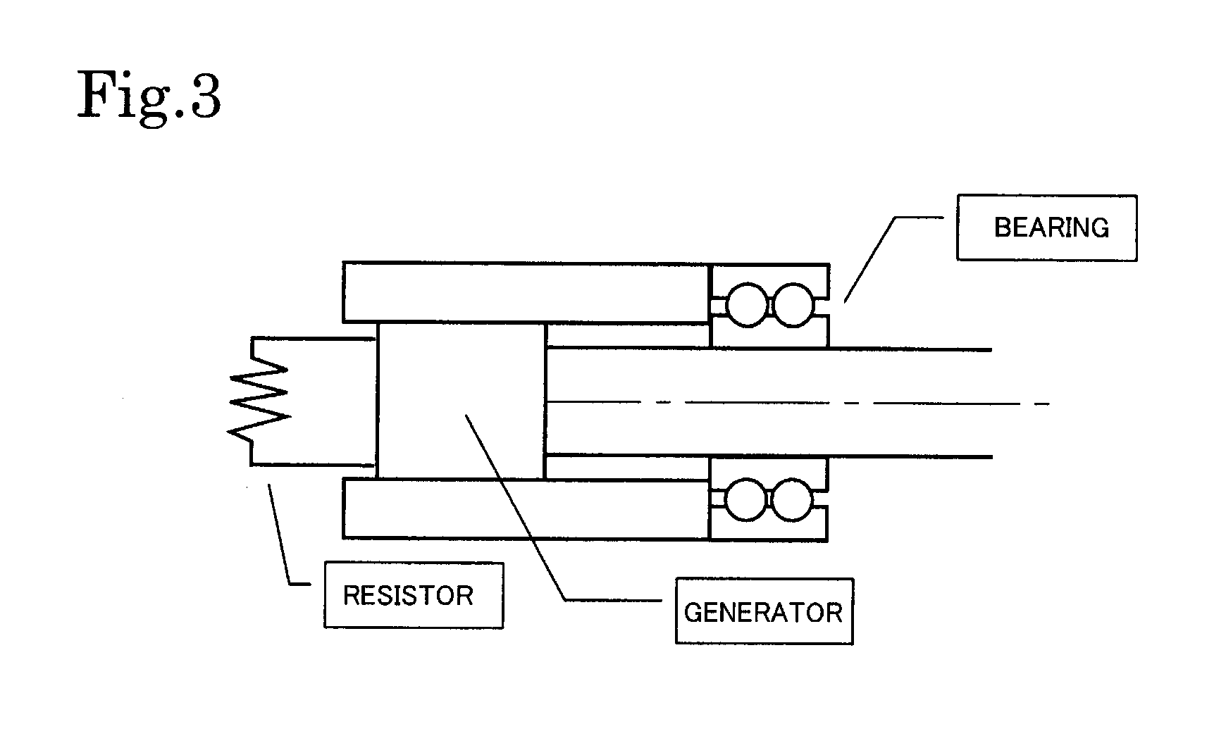
[0044]A flywheel of the present invention acts as an energy storing device when mounted on a vehicle. It is possible to construct an energy storage device from the flywheel by installing an electric motor-generator at the flywheel. The electric motor-generator can be separate from the flywheel or can be built in within the housing of the flywheel. Energy storage can then be carried out using the running energy of the flywheel. The electric motor-generator then operates so as to transfer energy with outside. A motor mounted on a rotating shaft of the flywheel then becomes an electric motor at the time of energy storage. The motor mounted on the rotating shaft of the flywheel then becomes a generator at the time of energy discharge. As disclosed in the background art, construction of energy storage devices employing flywheels is well-known to one skilled in the art. Energy storage devices ...


PUM


Abstract

The present invention controls rolling motion of a vehicle by eliminating the detrimental influence of gyro moment on the motion of the vehicle and actively using gyro moment generated by a flywheel constituting an energy storing device. The invention relates to an attitude control device for a vehicle mounted with a flywheel as an energy storage device, the flywheel being pivotally supported about first and second axes mutually orthogonal with each other, the flywheel being mounted on a body of the vehicle such that the first axis extends in a front-rear direction of the body, the attitude control device comprising locking means for locking movement of the flywheel about the first axis, wherein a rolling motion of the vehicle is controlled by locking the movement of the flywheel about the first axis using said locking means.

Description

TECHNICAL FIELD[0001]The present invention relates to an attitude control device, and particularly relates to a device for controlling attitude during the motion of vehicles and rolling stock such as automobiles, coupled vehicles such as large-type trucks and trailers, and railroad vehicle, and etc.BACKGROUND ART[0002]Energy storage devices that accumulate energy such as recovered brake energy temporarily in order to conserve energy for vehicles etc. have been taken note of. A flywheel device that stores rotational energy of a rotating body rotating at high speed is one such device. A flywheel can provide an energy storage device that accumulates energy acquired from a drive force transmission system of a vehicle as energy of rotation of a flywheel that is then discharged as necessary. For example, when a vehicle decelerates, kinetic energy of the vehicle is recovered via a drive force transmission system. Accumulated energy is then returned to the drive force transmission system so...

Claims


Application Information

Patent Timeline
IPC IPC(8): G01C19/26
CPCB61C17/06B61F5/22B62D37/00Y10T74/1204G01C19/02G01C19/065Y02T30/18B62D37/06Y02T30/00
Inventor SUDA, YOSHIHIROKOTANI, MANABU
Owner SUDA YOSHIHIRO
Learn More