Method for producing an antenna structure for an RFID device, and dry toner for use in producing such antenna structure

Inactive Publication Date: 2011-01-27
EASTMAN KODAK CO
View PDF7 Cites 16 Cited by
  • Summary
  • Abstract
  • Description
  • Claims
  • Application Information

AI Technical Summary

Benefits of technology

[0006]It is therefore an object of the present invention to provide a functional method for producing an antenna structur

Problems solved by technology

Such a process, however, necessitates the production of a suitable mask for the antenna structure, which is not cost effective in applications in which only a li

Method used


Image

  • Method for producing an antenna structure for an RFID device, and dry toner for use in producing such antenna structure
  • Method for producing an antenna structure for an RFID device, and dry toner for use in producing such antenna structure
  • Method for producing an antenna structure for an RFID device, and dry toner for use in producing such antenna structure

Examples


Embodiment Construction

[0015]The following description uses relative terms such as left, right, above and below which relative terms refer to the drawings and should not be construed to limit the application.

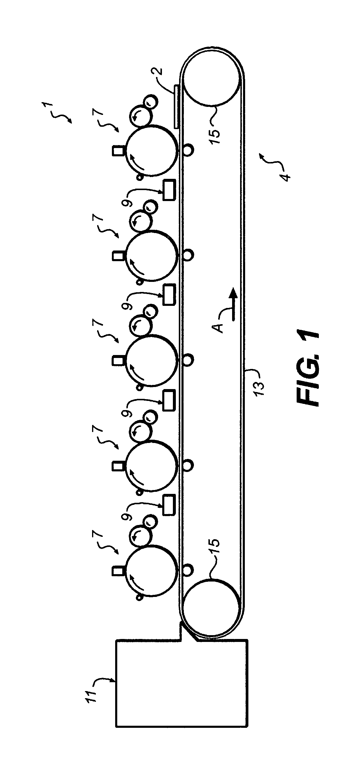
[0016]FIG. 1 illustrates a side elevational view of part of an electrophotographic printing apparatus 1, for printing onto a substrate 2, such as for example paper, packaging board, adhesive tags or any other suitable substrate. The printing apparatus 1 as shown has a substrate transport arrangement 4, five print modules 7, four charge neutralizing devices 9, and a fuser arrangement 11.

[0017]The substrate transport arrangement 4 is made of a transport belt 13, which is entrained about two rollers 15, at least one of which is coupled to a drive mechanism (not shown) to move the transport belt 13 in a circular path around the rollers 15, as indicated by arrow A.

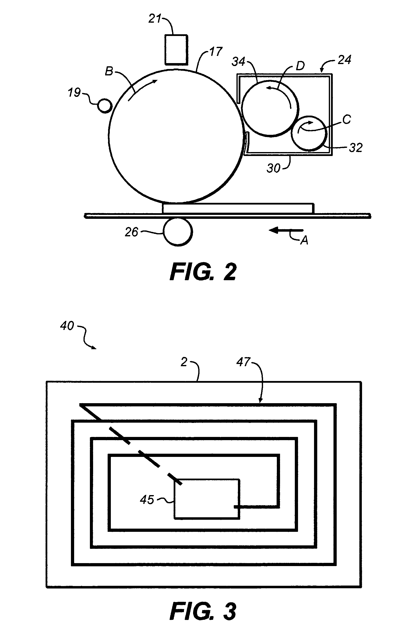
[0018]The five print modules 7, one of which is shown enlarged in FIG. 2, each have a photoconductor drum 17, a charge device 19, a selective di...


PUM

PropertyMeasurementUnit
Temperatureaaaaaaaaaa
Timeaaaaaaaaaa
Timeaaaaaaaaaa

Abstract

A method for producing an antenna structure for an RFID device, a dry toner for use in producing an antenna for an RFID device and a RFID device comprising an antenna structure made of fused toner are disclosed. In a method for producing an antenna structure for an RFID device, a dry toner comprising a polymeric binder and metallic particles is provided. The toner comprises particles having a resistance allowing triboelectric charging or a resistance allowing inductive charging, wherein said metallic particles are nanoparticles having a mean particle size below approximately 500 nm in at least one direction. In the method, a continuous layer of the dry toner is applied to a substrate in a desired shape of an antenna via an electrophotographic printing process, and subsequently the toner is fused to the substrate by heating the toner above its glass transformation temperature. The dry toner for use in producing an antenna for an RFID device comprises toner particles having a resistance allowing triboelectric charging or a resistance allowing inductive charging. The toner particles comprise a polymeric binder and metallic particles, wherein said metallic particles are nanoparticles having a mean particle size below approximately 500 nm in at least one direction.

Description

BACKGROUND OF THE INVENTION[0001]The present invention relates to a method for producing an antenna structure for an RFID device, and a dry toner for use in producing an antenna for an RFID device. The present invention also relates to an RFID device comprising an antenna structure made of fused toner.[0002]In different environments radio frequency identification devices commonly also referred to as RFID devices or tags are known. RFID-tags are for example known in identifying and tracking stock in a warehouse. The RFID-tags typically have an electronic circuit formed on a silicon chip and an antenna structure tuned to a specific frequency. Coupling to a reading device is typically done inductive or electromagnetic.[0003]As there is a tendency to replace current barcode identification of products by RFID devices, there is a need to lower the cost for producing the RFID device.[0004]One method proposed for producing the antenna structure for an RFID device uses a screen printing proc...

Claims


Application Information

Patent Timeline
IPC IPC(8): G06K19/067G03G13/08G03G9/08G03G9/087
CPCG03G7/0093H05K2203/0517G03G9/0821G03G9/0823G03G9/0832G03G9/08755G03G9/08766G03G9/08793G03G9/08795G03G9/08797G03G9/0902G03G9/09708G06K19/07749H01Q1/2225H05K3/1266G03G9/0819G03G15/224G03G15/6585G03G15/6591
Inventor SCHULZE-HAGENEST, DETLEFTYAGI, DINESH
Owner EASTMAN KODAK CO
Why Eureka
Try Eureka