Bicycle Rear Suspension Linkage

a rear suspension and bicycle technology, applied in the field of bicycle rear suspension linkage, can solve the problems of not being able to address many performance issues, wasting energy expended by the rider of the bike, and imparting torque on the pedals, etc., to achieve optimized shock rate, small change in rate, and improve pedaling performance

Active Publication Date: 2011-01-27
SINE SUSPENSION LLC
View PDF11 Cites 20 Cited by
  • Summary
  • Abstract
  • Description
  • Claims
  • Application Information

AI Technical Summary

Benefits of technology

[0026]It is a further object of the invention to provide an optimized rear wheel travel path that allows for better pedaling performance throughout the range of suspension travel.
[0027]It is a further object of the invention to provide an optimized shock rate that advantageously provides for small changes in rate.
[0028]It is a further object of the invention to provide an optimized shock rate that advantageously changes sign more than once and articulates the rear wheel in a controlled and preferential non-arc travel path.

Problems solved by technology

While the single pivot systems are very simple, relatively easy to design, and adequately handle small bumps, they fail to address many performance issues.
Likewise, compression and extension of the suspension can impart torque on the pedals and supply unwanted force to the rider's legs.
Thus, some of the energy expended by the rider of the bike is used needlessly wasted, either compressing or extending the suspension of the system, or resisting unwanted pedal rotation imparted by the suspension.
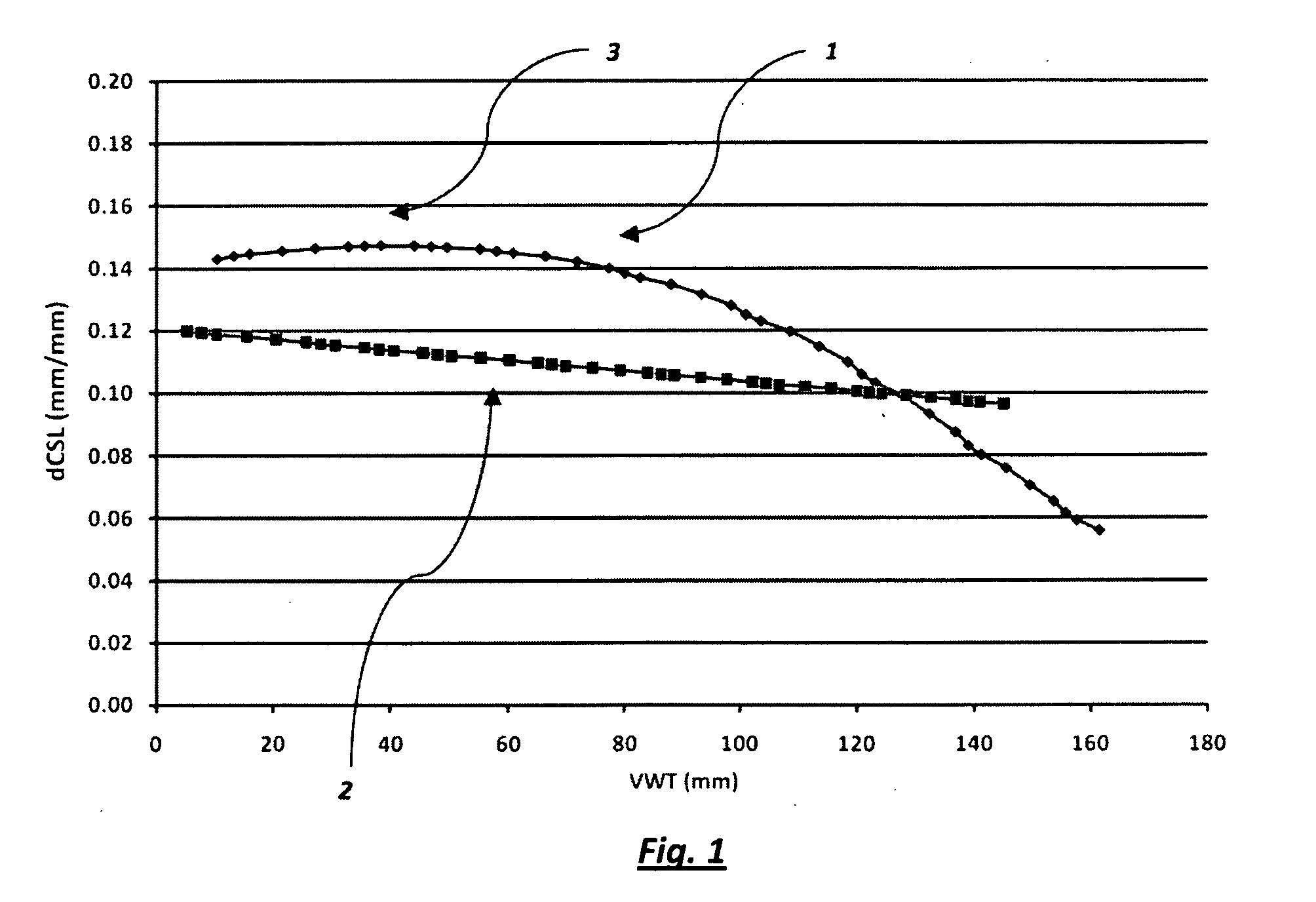
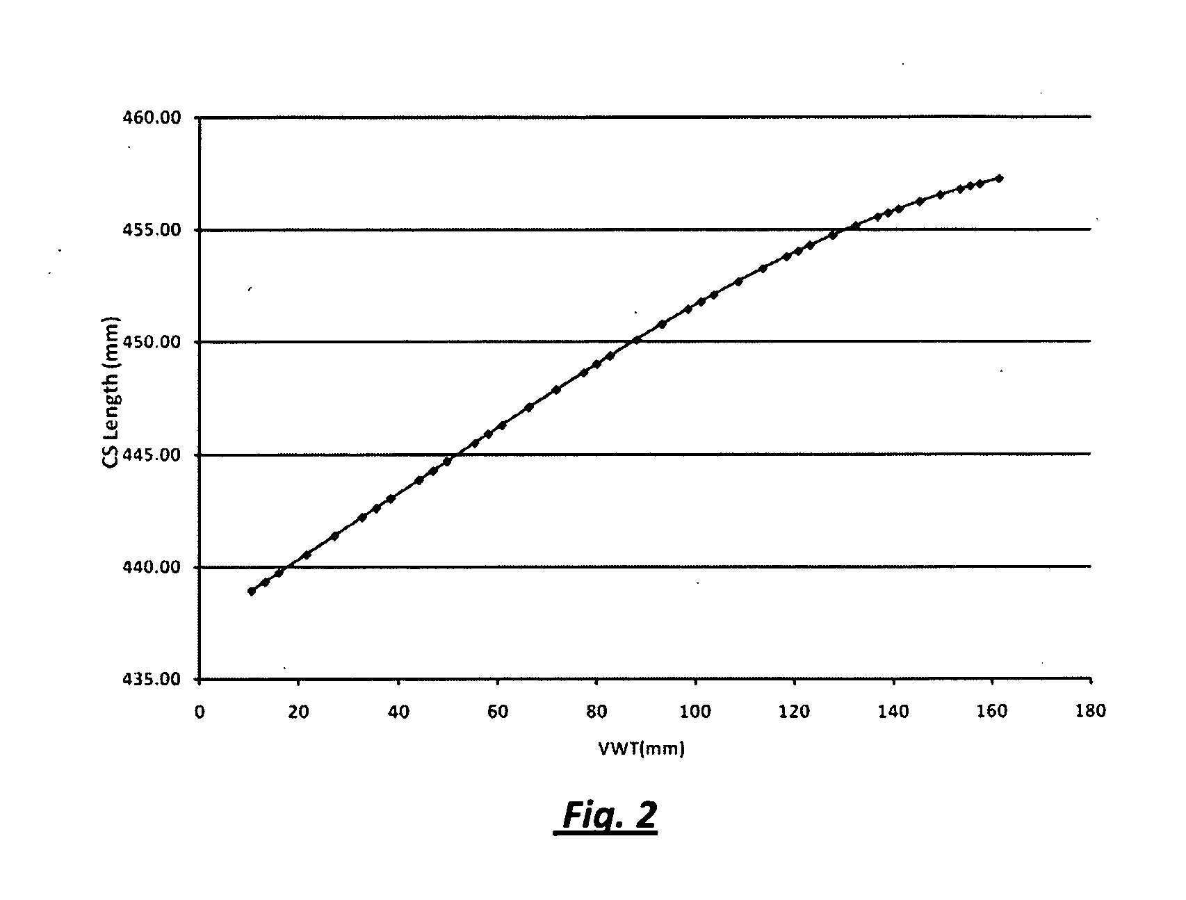
In single pivot systems there is no means for varying the rate of chainstay lengthening through the travel of the suspension.
Thus, if the rate of chainstay lengthening is high, so as to decrease unwanted pedal rotation and increase the anti-squat characteristics of the suspension system, the result will be excessive chainstay lengthening at full compression and the application of excessive torque to the pedal crankarms.
As a result, ineffective compromises in the suspension system's performance must always be struck.
These compromises include excessive chainstay lengthening resulting in unwanted torque applied to the bicycle's pedal crankarms, extension or compression of the suspension system due to pedal forces, and extension or compression of the suspension system during acceleration and braking due to weight transfer.
Additionally, as may be apparent from the above, any system that articulates the rear wheel along an arc forfeits the performance benefits associated with articulating the rear wheel along a controlled, and preferential travel path.
These systems provide challenges to the suspension designer, in that there is typically a tradeoff between optimally manipulating the rear wheel travel path and controlling the change in the shock rate.
Systems that vary the rear wheel travel path to a greater extent generally must also vary the shock rate to a great extent, which leads to undesirable bump absorption characteristics.
These systems allow for more complicated leverage ratios than a single pivot system, which results in increased tunability of the shock absorber leverage rate.
However, even with this improved system, the rear wheel still moves in an arc, resulting in many of the same compromises in performance from which the single pivot suspension systems suffer.
While there is a great variety in these linkage systems, most are four-bar systems that articulate the rear wheel in a more complicated manner than is allowed with a single pivot system.
Because this class of four bar linkage systems articulates the rear wheel in a large radius arc, the employment of an optimal amount of chainstay lengthening in the early part of the rear wheel's travel results in an unacceptable total amount of chainstay lengthening when the system is fully compressed.
This design suffers from the drawback that chainstay lengthening effects are minimally utilized and instead the suspension system is designed to provide an optimized anti-squat behavior for an arbitrary constant pedaling input force and gear.
In practice, both the pedaling input force and gear are greatly variable and thus an assumption that they are an arbitrary constant is invalid and suboptimal.
The distance between the pivots on the small link is significantly larger than 15 mm, and thus suffers from a weight disadvantage.
This design moves the rear wheel in a very large arc, and as such suffers from the typical performance drawbacks experienced by other similar systems, such as the inability to control the chainstay lengthening effect and provide for an optimized rear wheel travel path that reduces pedaling induced compression and extension of the suspension.
Further, due to the interaction between the linkage members of the suspension system, the suspension system once tuned to provide the described s-shaped rear wheel travel path, produces a shock rate with detrimentally high rates of change.
Finally, due to the length requirements of the lower linkage member, it is impractical to utilize a small eccentric as a linkage member and benefit from the significant weight saving advantages that go along with a small eccentric linkage member.
However, this motion of the pedal crank axis relative to the seat of the bicycle is perceptible to the rider, and also affects pedaling performance as the relationship between the seat and the pedals changes as the suspension is compressed.
Thus, all of the prior art suffers from a serious performance drawback: when the suspension system is configured in such a manner that the overall chainstay lengthening effect is small enough to prevent unwanted feedback to the rider's pedaling motion when the suspension system is fully compressed, the system does not offer enough chainstay lengthening effect when the suspension system is in its statically loaded sag state.
None of the linkage systems currently in use or previously described drastically alter the rear wheel path to quickly move from a high rate of chainstay lengthening in the early portion of the rear wheel's motion and to the statically loaded sag point to a rate of very low chainstay lengthening after a specified point in the rear wheel's travel in close proximity to the sag point.

Method used


Image

  • Bicycle Rear Suspension Linkage
  • Bicycle Rear Suspension Linkage
  • Bicycle Rear Suspension Linkage

Examples


Embodiment Construction

[0052]The following description is presented to enable a person of ordinary skill in the art to make and use various aspects and examples of the present invention. Descriptions of specific materials, techniques, and applications are provided only as examples. Various modifications to the examples described herein will be readily apparent to those of ordinary skill in the art, and the general principles defined herein may be applied to other examples and applications without departing from the spirit and scope of the invention. Thus, the present invention is not intended to be limited to the examples described and shown, but is to be accorded the scope consistent with the appended claims.

[0053]Many bicycles (bikes) have a rear suspension system that guides the rear wheel of the bike to move along a preferred rear wheel axle path. As the suspension guides the rear wheel in this way, there is an associated change in the chainstay length (CSL), that is, in the distance from the pedal ax...


PUM


Abstract

A bicycle comprising a front triangle and a rear wheel having a rear wheel axis, a rear wheel suspension system further comprising a link further comprising a first pivotal axis for connection to said front triangle and a second pivotal axis for connection to a rear wheel swingarm, wherein the distance from said second pivotal axis to a first vertical plane decreases during a first portion of suspension compression and increases during a second portion of suspension compression; and wherein said first vertical plane is defined as a plane which is perpendicular to the ground and offset in the direction of the rear wheel with respect to the first and second pivotal axis. During the first portion of suspension compression and during the second portion of suspension compression the front triangle remains stationary with respect to the first vertical plane.

Description

RELATED APPLICATIONS[0001]This application is related to previously filed U.S. provisional patent application Ser. No. 61 / 124,789, filed Apr. 17, 2008, entitled “Bicycle Suspension System”, which is incorporated by reference herein as if set out in full.[0002]Further, this application is related to two U.S. nonprovisional patent applications filed on Apr. 17, 2009, entitled “Bicycle Rear Suspension System” (application Ser. No. 12 / 426,042) and “Bicycle Rear Suspension System Linkage” (application Ser. No. 12 / 426,037), and which are hereby incorporated by reference herein in its entirety.BACKGROUND[0003]1. Field of the Invention[0004]The present invention relates to a new bicycle rear suspension system, and in particular to a four-bar suspension system that offers improved pedaling and bump absorption performance by means of controlling the rate of chainstay lengthening through the use of a small eccentric mechanism located in close proximity to the bicycle chain line.[0005]2. Backgr...

Claims


Application Information

Patent Timeline
Patent Type & Authority Applications(United States)
IPC IPC(8): B62K3/04
CPCB62K25/286
Inventor BEALE, LUTHER M.EARLE, DAVID M.
Owner SINE SUSPENSION LLC
Why Eureka
Try Eureka