Telescopic pipe for electronic apparatus

a technology of electronic equipment and telescopic pipes, applied in mechanical equipment, screw threaded joints, cleaning equipment, etc., can solve the problems of air leakage between the inner and outer pipes, deformation of operation ability, and considerable wear of sealing portions, and achieve enhanced sealing force

Inactive Publication Date: 2011-01-27
SAMSUNG GWANGJU ELECTRONICS CO LTD
View PDF2 Cites 10 Cited by
  • Summary
  • Abstract
  • Description
  • Claims
  • Application Information

AI Technical Summary

Benefits of technology

[0015]In one general aspect, there is provided a telescopic pipe for an electronic apparatus, which includes an outer pipe, an inner pipe with fixing grooves, inserted into the outer pipe, a holder pipe fixed to one side of the outer pipe, a handle pipe configured to surround the holder pipe, and a sealing member formed on an outer surface of the inner pipe to seal the space between the outer and inner pipes. The sealing member has at least one sealing portion of which a shape is changed by a negative pressure produced in the interior of the inner pipe so that its sealing force is enhanced.

Problems solved by technology

Because of this frictional contact, the sealing portion may become considerably worn from use over time, and air may leak between the inner and outer pipes.
Due to the frictional force between the outer pipe and the sealing portion of the sealing member having the outer pipe fixed thereto, much force is applied when the telescopic pipe is operated, and operational ability may be degraded.
Therefore, a gap between the inner and outer pipes may be formed, and air may be leaked through the gap.
However, in the aforementioned telescopic pipes, the fixing member with the roller shape may be easily separated from the fixing groove along the gentle slope of the sides of the fixing groove regardless of user's intention, and it may be difficult to firmly fix the inner pipe to the outer pipe.
Therefore, it may be difficult to control the telescopic pipes.

Method used


Image

  • Telescopic pipe for electronic apparatus
  • Telescopic pipe for electronic apparatus
  • Telescopic pipe for electronic apparatus

Examples


Embodiment Construction

[0049]The following detailed description is provided to assist the reader in gaining a comprehensive understanding of the methods, apparatuses, and / or systems described herein. Accordingly, various changes, modifications, and equivalents of the systems, apparatuses, and / or methods described herein will be suggested to those of ordinary skill in the art. The progression of processing steps and / or operations described is an example; however, the sequence of and / or operations is not limited to that set forth herein and may be changed as is known in the art, with the exception of steps and / or operations necessarily occurring in a certain order. Also, descriptions of well-known functions and constructions may be omitted for increased clarity and conciseness.

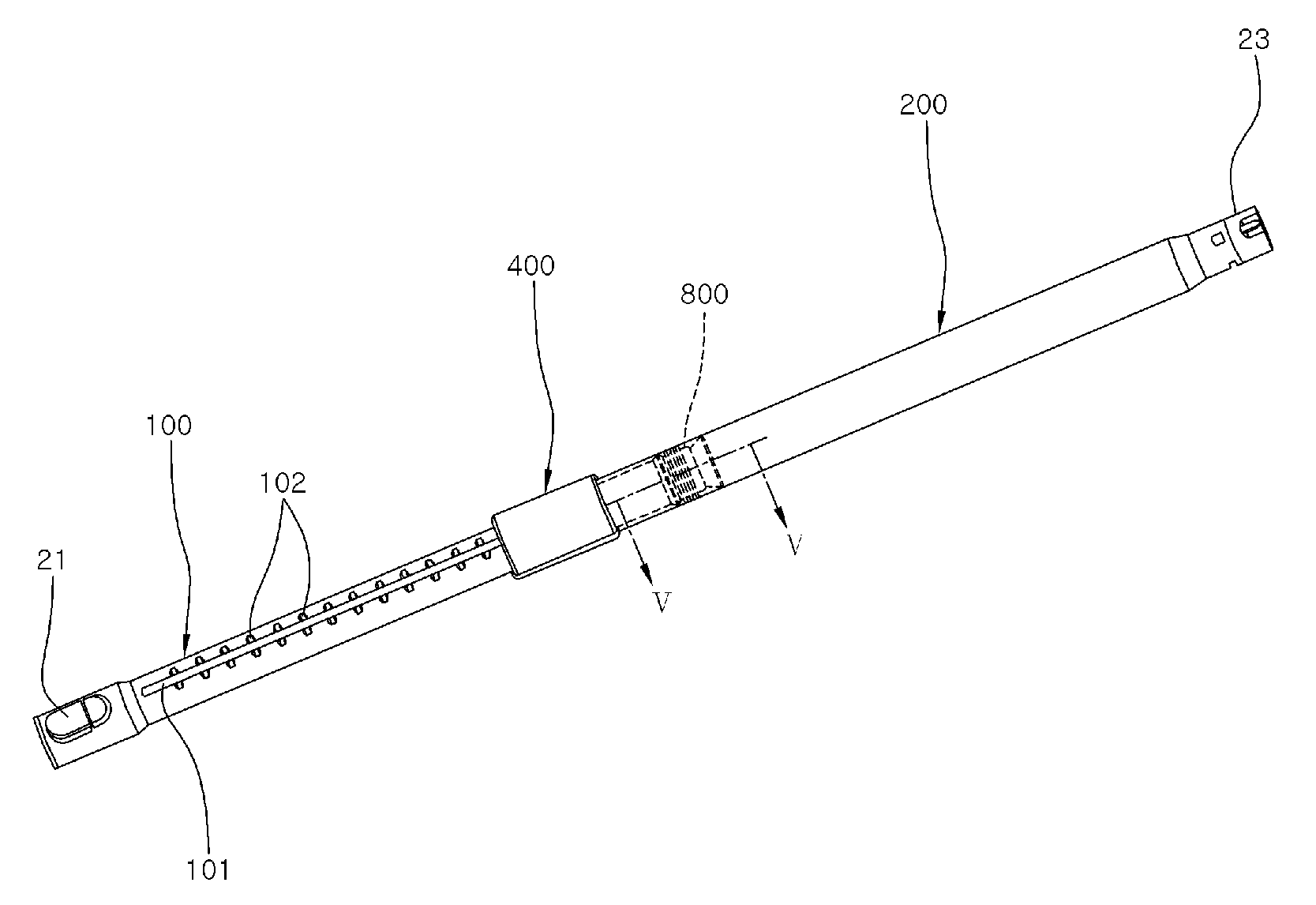
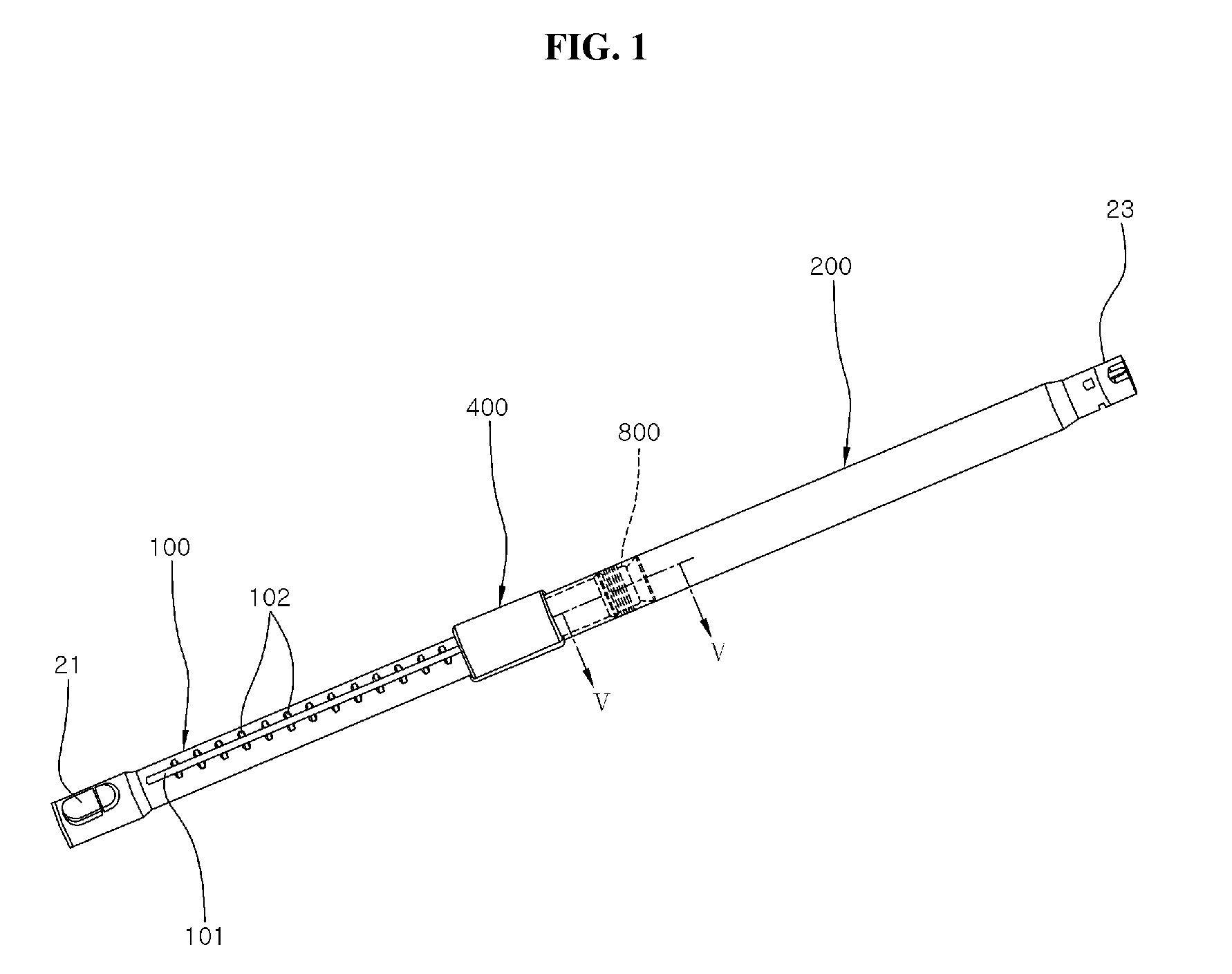
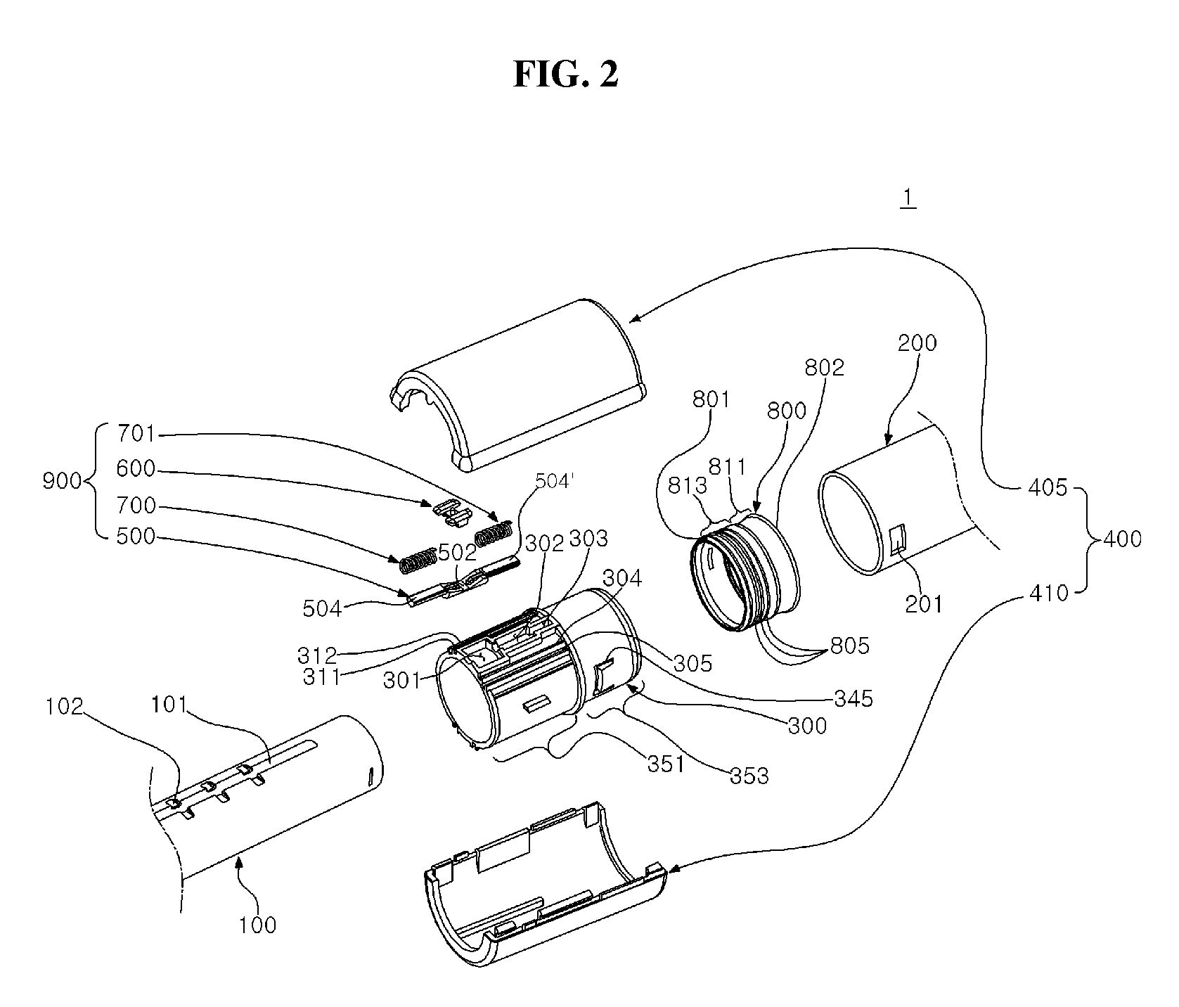
[0050]FIG. 1 illustrates a perspective view of an example of a telescopic pipe for an electronic apparatus. FIG. 2 illustrates an exploded perspective view of an example of the telescopic pipe shown in FIG. 1. FIG. 3 illustrates an en...


PUM


Abstract

A telescopic pipe for an electronic apparatus is provided. The telescopic pipe for the electronic apparatus includes an outer pipe, an inner pipe with fixing grooves, inserted into the outer pipe; a holder pipe fixed to one side of the outer pipe, a handle pipe formed to surround the holder pipe, and a sealing member formed on an outer surface of the inner pipe to seal the space between the outer and inner pipes. In the telescopic pipe, the sealing member has at least one sealing portion of which a shape is changed by a negative pressure produced in the interior of the inner pipe so that its sealing force is enhanced.

Description

CROSS-REFERENCE TO RELATED APPLICATIONS[0001]This application claims benefit under 35 U.S.C. § 119(e) of U.S. Provisional Application No. 61 / 228,211, filed on Jul. 24, 2009, in the United States Patent and Trademark Office, and under 35 U.S.C. § 119(a) of Korean Patent Application No. 10-2009-0098667, filed on Oct. 16, 2009, in the Korean Intellectual Property Office, the entire disclosures of which are incorporated herein by reference for all purposes.BACKGROUND[0002]1. Field[0003]The following description relates to a telescopic pipe, and more particularly, to a telescopic pipe for an electronic apparatus.[0004]2. Description of the Related Art[0005]Telescopic pipes for use with an electronic apparatus are known. Generally, a telescopic pipe for an electronic apparatus has a sealing member to restrict leakage of air between inner and outer pipes. The telescopic pipe may be configured to have a protruding projection formed at one end of the sealing member or to have the shape of an...

Claims


Application Information

Patent Timeline
Patent Type & Authority Applications(United States)
IPC IPC(8): A47L9/24F16L27/12
CPCA47L9/244
Inventor JEON, KYONG-HUILIM, WON-KYU
Owner SAMSUNG GWANGJU ELECTRONICS CO LTD
Why Eureka
Try Eureka