Rechargeable battery and method of assembling for the same

a rechargeable battery and assembly method technology, applied in the field of rechargeable batteries, can solve the problems of gasket surrounding the electrode terminal, the terminal hole of the cap plate, and the electrolyte solution contained in the case may leak through the gaps of the assembled portions, so as to prevent short circuit

Inactive Publication Date: 2006-09-14
SAMSUNG SDI CO LTD
View PDF6 Cites 8 Cited by
  • Summary
  • Abstract
  • Description
  • Claims
  • Application Information

AI Technical Summary

Benefits of technology

[0017] Embodiments of the present invention provide a rechargeable battery having a cap assembly capable of increasing a sealing force of a cap plate, a gasket, and an electrode terminal; and / or a method of assembling the rechargeable battery.
[0022] Another embodiment of the present invention provides a rechargeable battery including: an electrode assembly having two electrodes and a separator interposed between the two electrodes to prevent short circuit between the two electrodes; a case (e.g., a can) having an opening through which the electrode assembly is accommodated; and a cap assembly covering the can, the cap assembly having a plate-shaped cap plate on which a terminal hole is formed, a tube-shaped insulating gasket inserted into the terminal hole, and an electrode terminal passing through the insulating gasket, wherein the electrode terminal is forcibly inserted into the insulating gasket, and the insulating gasket is forcibly inserted into the terminal hole of the cap plate.

Problems solved by technology

However, in the conventional cap assembly, gaps may occur among the assembled portions of the electrode terminal, the gasket surrounding the electrode terminal, and the terminal hole of the cap plate.
In addition, the electrolyte solution contained in the case may leak out through the gaps of the assembled portions.

Method used


Image

  • Rechargeable battery and method of assembling for the same
  • Rechargeable battery and method of assembling for the same
  • Rechargeable battery and method of assembling for the same

Examples


Embodiment Construction

[0028] In the following detailed description, certain exemplary embodiments of the present invention are shown and described, by way of illustration. As those skilled in the art would recognize, the described exemplary embodiments may be modified in various ways, all without departing from the spirit or scope of the present invention. Accordingly, the drawings and description are to be regarded as illustrative in nature, rather than restrictive.

[0029] Now, a rechargeable battery according to an embodiment of the present invention will be described in more detail with reference to FIGS. 1, 2, and 3.

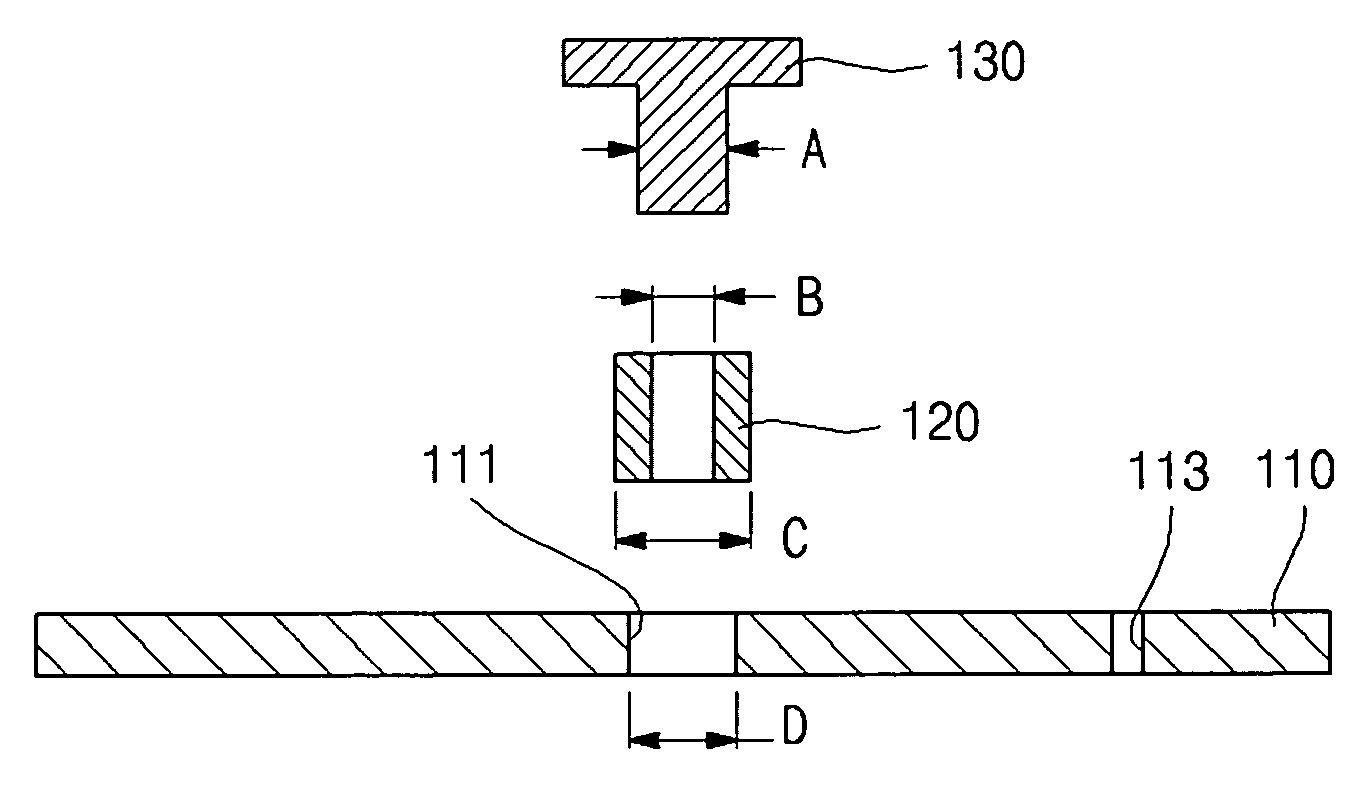
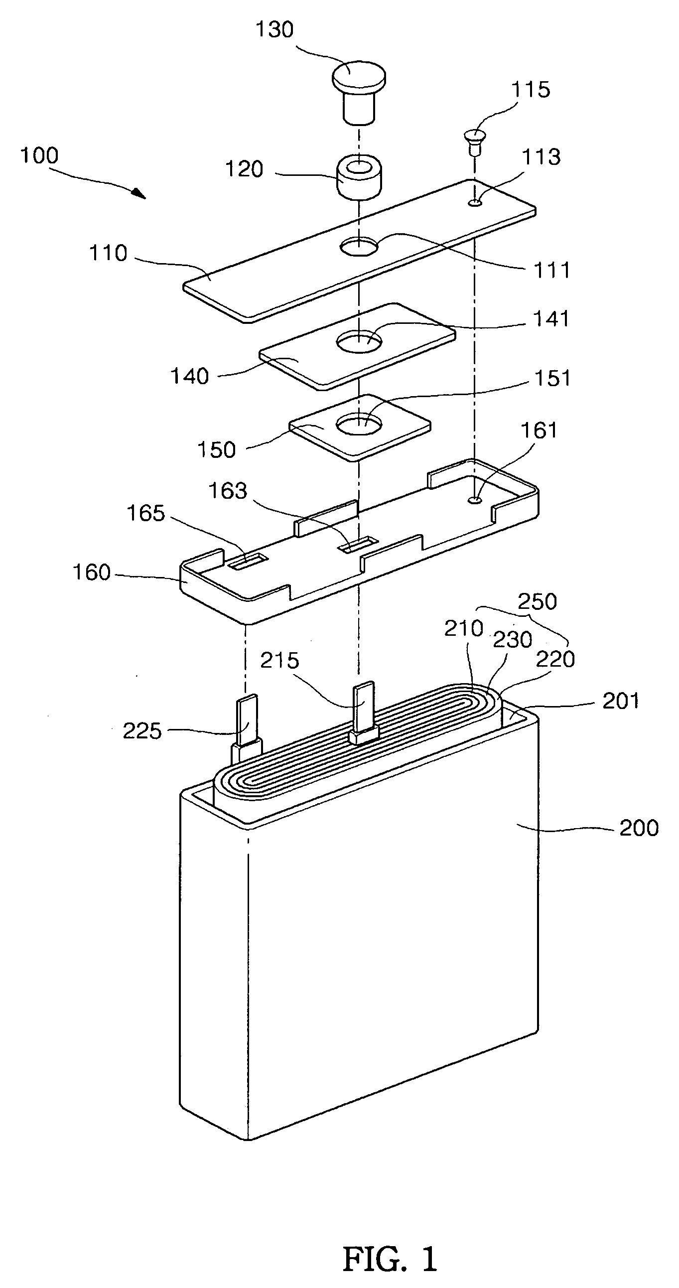
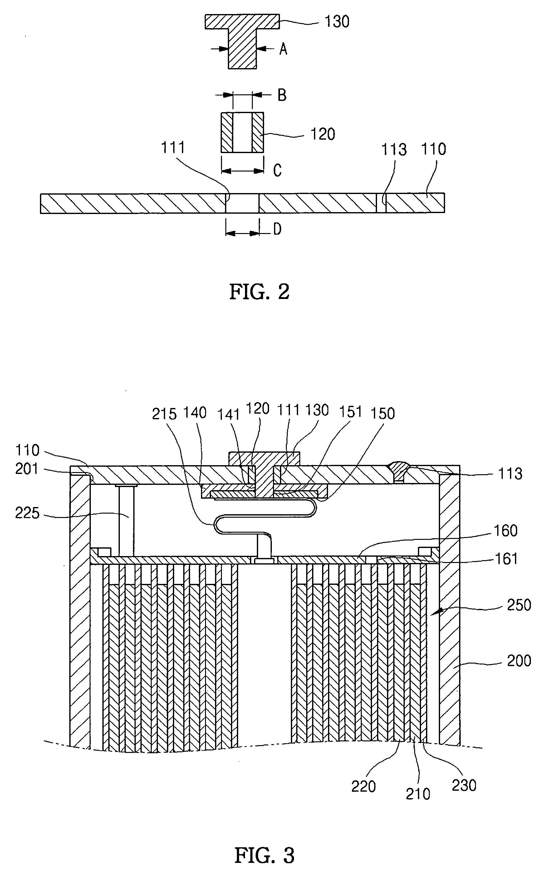
[0030]FIG. 1 is a perspective exploded view showing a rechargeable battery according to the embodiment of the present invention. FIG. 2 is a view showing an assembling relation of parts of the rechargeable battery according to the embodiment of the present invention. FIG. 3 is a cross-sectional view showing of the rechargeable battery according to the embodiment of the present invention....


PUM

PropertyMeasurementUnit
operating voltageaaaaaaaaaa
inner diameteraaaaaaaaaa
outer diameteraaaaaaaaaa

Abstract

A rechargeable battery and a method of assembling the rechargeable battery. The method includes the steps of: accommodating an electrode assembly into a case, the electrode assembly having first and second electrode taps protruding therefrom; forcibly inserting an electrode terminal into an insulating gasket, the insulating gasket having an inner diameter smaller than an outer diameter of the electrode terminal; forcibly inserting the insulating gasket into a terminal hole in a cap plate of a cap assembly; and sealing the case with the cap assembly. Accordingly, it is possible to increase a sealing force between the case and the cap assembly and effectively insulate the electrode terminal from the cap plate.

Description

CROSS-REFERENCE TO RELATED PATENT APPLICATION [0001] This application claims priority to and the benefit of Korean Patent Application No. 10-2005-0019836, filed on Mar. 9, 2005, in the Korean Intellectual Property Office, the entire content of which is incorporated herein by reference. BACKGROUND OF THE INVENTION [0002] 1. Field of the Invention [0003] The present invention relates to a rechargeable battery, and, more particularly, to a rechargeable battery having a cap assembly covering a case accommodating an electrode assembly. [0004] 2. Description of Related Art [0005] Recently, a large number of compact and lightweight electric or electronic apparatuses such as cellular phones, notebooks, and camcorders have been actively developed and produced. These portable electric or electronic apparatuses are provided with battery packs, so that these apparatuses can operate without separate power supplies. A battery pack includes at least one battery for outputting a voltage having a pr...

Claims


Application Information

Patent Timeline
Patent Type & Authority Applications(United States)
IPC IPC(8): H01M10/04H01M2/08H01M50/176H01M50/184H01M50/188H01M50/193H01M50/553H01M50/564
CPCH01M2/021H01M2/06H01M2/08Y10T29/4911H01M10/0436H01M10/0525H01M10/0587H01M2/30Y02E60/10Y02P70/50H01M50/184H01M50/564H01M50/193H01M50/553H01M50/176H01M50/188H01M50/172H01M50/183H01M50/543H01M50/103
Inventor CHO, SUNG JAEJUNG, SANG SOK
Owner SAMSUNG SDI CO LTD
Why Eureka
Try Eureka