Braking system with linear actuator

a linear actuator and braking system technology, applied in the field of braking systems, can solve the problems of requiring pedal pumping, difficult foot pressure generation, and inability to easily adapt the hydraulic system to additionally control an anti-skid control system, etc., to achieve the effect of increasing and decreasing the brake pressure and increasing the brake pressur

Inactive Publication Date: 2011-01-27
GENERAL ATOMICS
View PDF73 Cites 27 Cited by
  • Summary
  • Abstract
  • Description
  • Claims
  • Application Information

AI Technical Summary

Benefits of technology

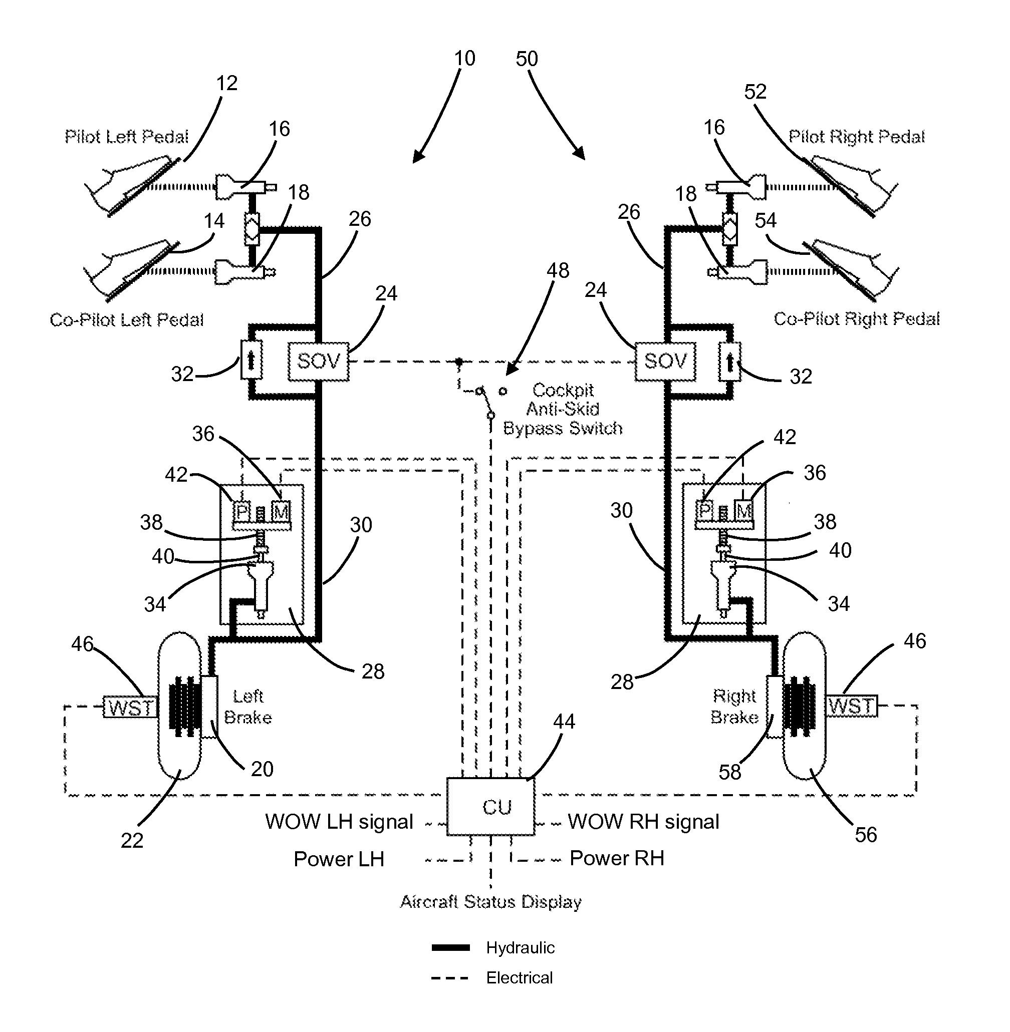
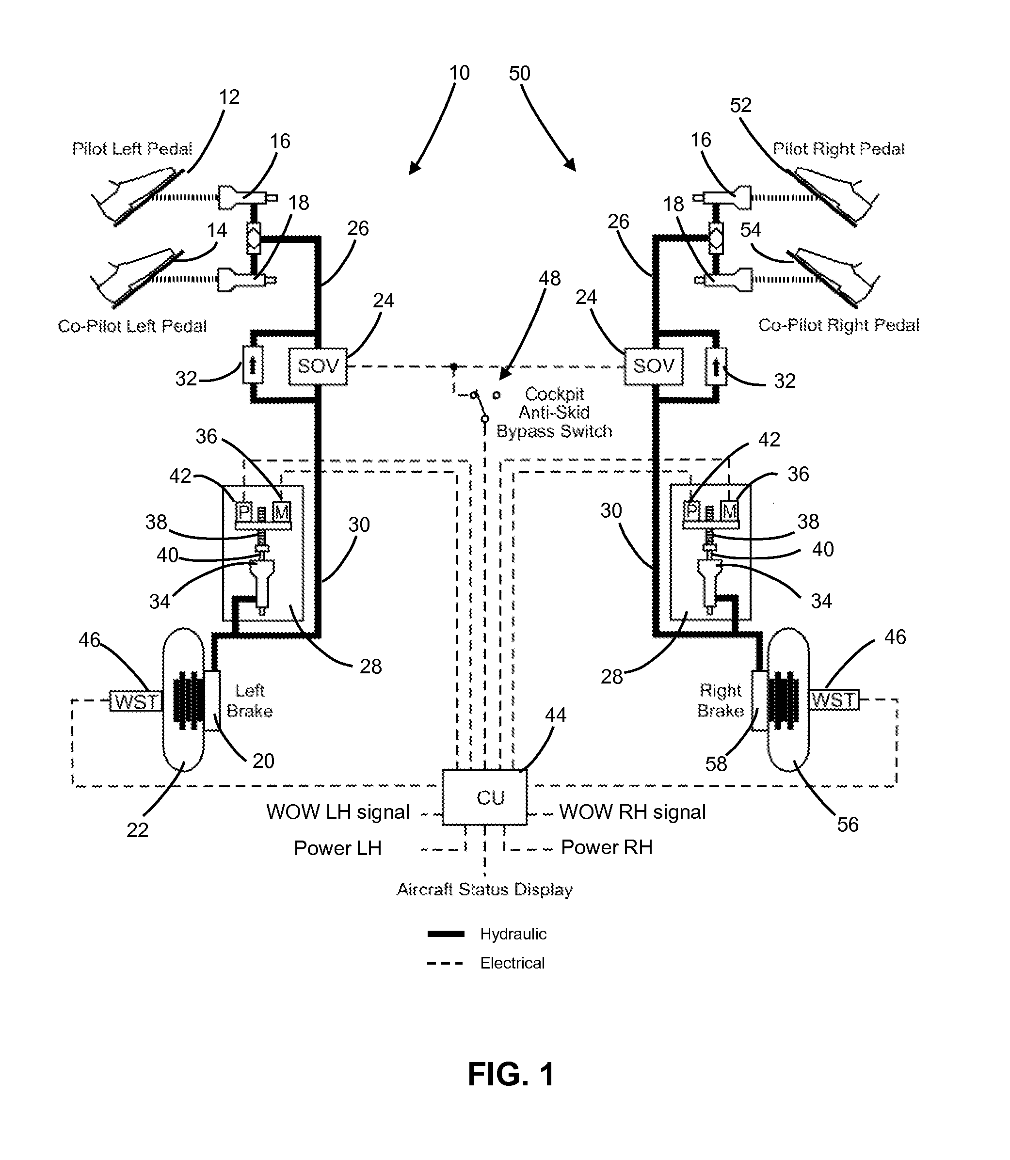
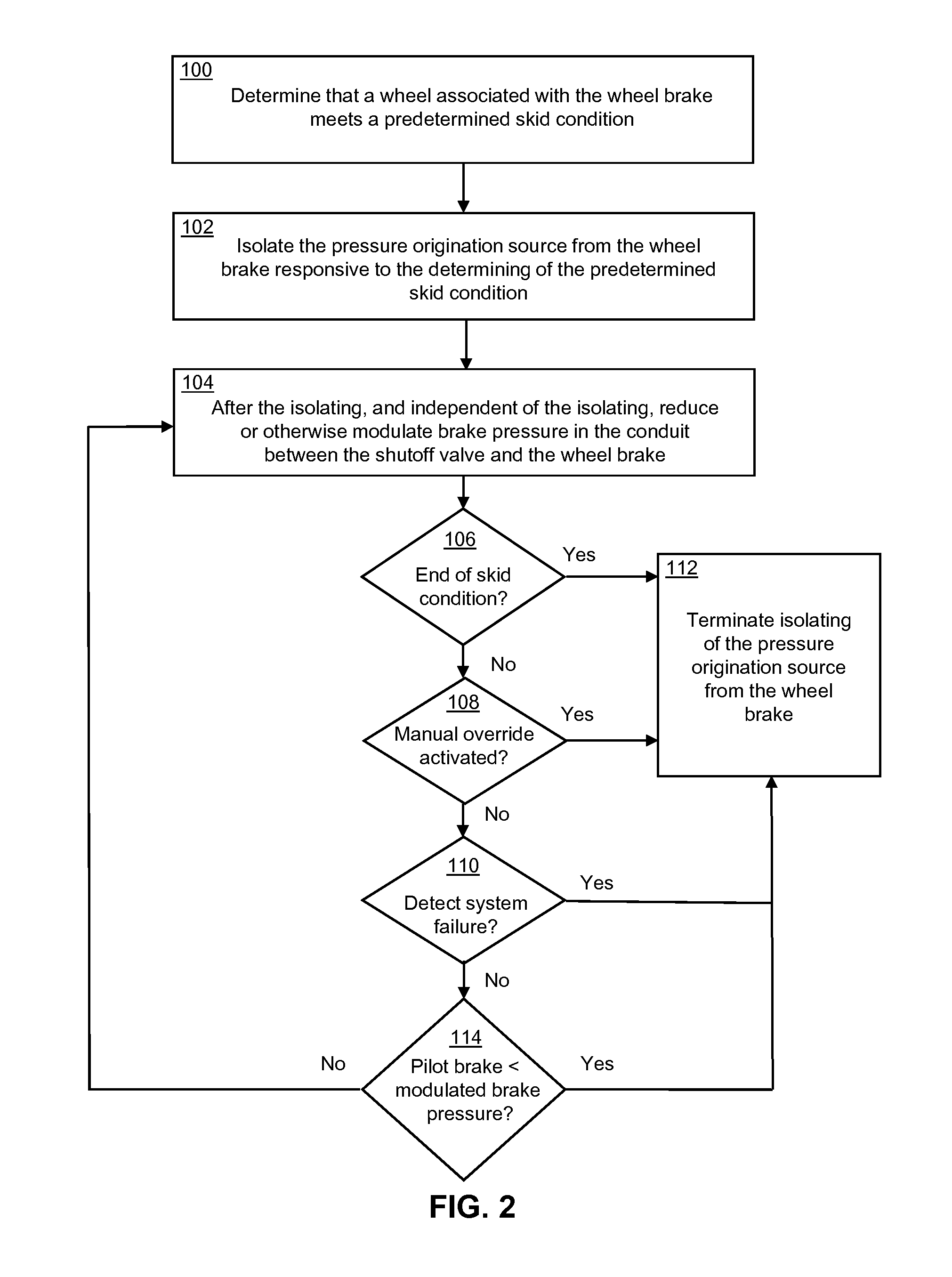
In yet another embodiment, the invention can be characterized as a brake pressure control system having a shutoff valve located in a hydraulic conduit between a pressure origination source and a wheel brake, wherein the shutoff valve is configured to selectively isolate the pressure origination source from the wheel brake responsive to an indication that a wheel associated with the wheel brake meets a skid condition, and an actuator assembly coupled to the shutoff valve via a portion of the hydraulic conduit and comprising an actuator displaceable to regulate fluid brake pressure within the hydraulic conduit after the shutoff valve isolates the pressure origination source from the wheel brake. The actuator assembly is also structured to effect displacement of the actuator for increasing and decreasing the brake pressure. The system further includes a controller coupled to the shutoff valve and the power source and configured to determine if the skid condition has be

Problems solved by technology

One drawback with this arrangement is that increasing numbers of modern aircraft either do not have a central hydraulic system or the hydraulic system cannot be easily adapted to additionally control an anti-skid control system.
Many brake systems require a large degree of ankle rotation by the pilot to displace enough fluid to fill the brake and effect the necessary braking, and for many pilots, as the pedal angle increa

Method used


Image

  • Braking system with linear actuator
  • Braking system with linear actuator
  • Braking system with linear actuator

Examples


Embodiment Construction

The following description is not to be taken in a limiting sense, but is made merely for the purpose of describing the general principles of exemplary embodiments. The scope of the invention should be determined with reference to the claims.

Many of the functional units described in this specification have been labeled as modules, in order to more particularly emphasize their implementation independence. For example, a module may be implemented as a hardware circuit comprising custom VLSI circuits or gate arrays, off-the-shelf semiconductors such as logic chips, transistors, or other discrete components. A module may also be implemented in programmable hardware devices such as field programmable gate arrays, programmable array logic, programmable logic devices or the like.

Modules may also be implemented in software for execution by various types of processors. An identified module of executable code may, for instance, comprise one or more physical or logical blocks of computer instru...


PUM


Abstract

Various brake control systems and methods are provided herein. In one implementation, a brake pressure control system having a shutoff valve (24) in a hydraulic conduit (26, 30) between a pressure origination source (16, 18) and a wheel brake (20), the shutoff valve selectively isolates the pressure origination source from the brake responsive to an indication that a wheel associated with the brake meets a skid condition, and an actuator assembly (28) comprising an actuator (34) that regulates fluid brake pressure after the shutoff valve isolates the pressure origination source from the brake. The actuator assembly operates independently of the shutoff valve and is coupled to the hydraulic conduit between the shutoff valve and the brake. The actuator assembly also effects displacement of the actuator for increasing and decreasing brake pressure. A controller (44) determines if the skid condition has been reached and controls the shutoff valve and the actuator assembly based upon the skid condition.

Description

BACKGROUND OF THE INVENTION1. Field of the InventionThe present invention relates generally to braking systems, and more specifically to braking systems for aircraft. Even more specifically, the present invention relates to a braking system for aircraft using a linear actuator.2. Discussion of the Related ArtAnti-skid braking control systems have been in widespread use for many years. Such braking control systems are implemented in various applications including vehicles and aircraft. In the simplest sense, an anti-skid braking control system compares the speed of an aircraft, for example, derived from a wheel speed sensor (and wheel / tire radius) to the aircraft speed typically derived from a secondary or reference source. If the wheel is determined to be skidding or approaching a skid threshold, then brake pressure applied to the wheel is released and the wheel is allowed to spin back up to the appropriate speed. In this manner, anti-skid control is achieved by controlling the hydr...

Claims


Application Information

Patent Timeline
IPC IPC(8): B64C25/46B60T8/36B60T8/176B64C25/42B60T13/10B60T13/66
CPCB60T8/1703B64C25/46B60T8/4266B60T8/325B60T8/441
Inventor KING, JOHN C.SHEA, MARK A.
Owner GENERAL ATOMICS
Why Eureka
Try Eureka