Characteristic acquisition device, method and program
a technology of acquisition device and acquisition method, applied in the field of characteristic acquisition device and method, can solve the problems of phase error and existing amplitude error of multiple d/a converters
- Summary
- Abstract
- Description
- Claims
- Application Information
AI Technical Summary
Problems solved by technology
Method used
Image
Examples
first embodiment
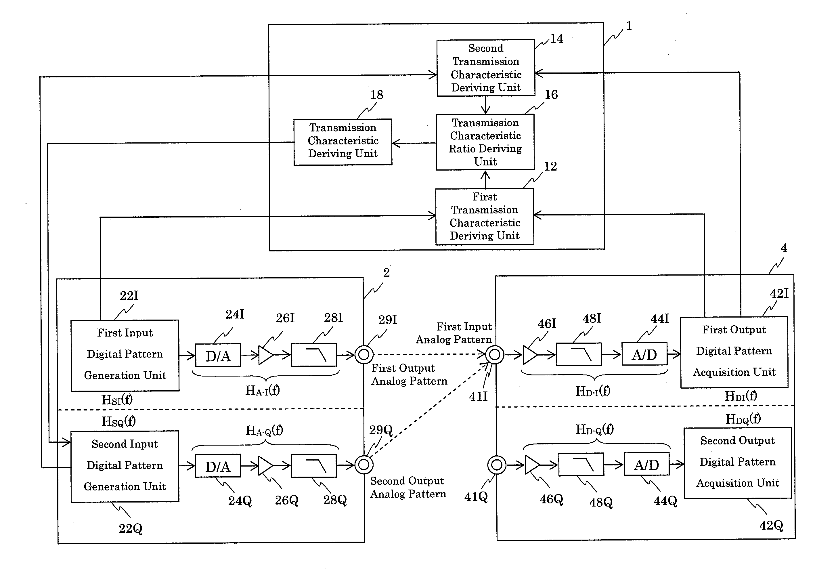
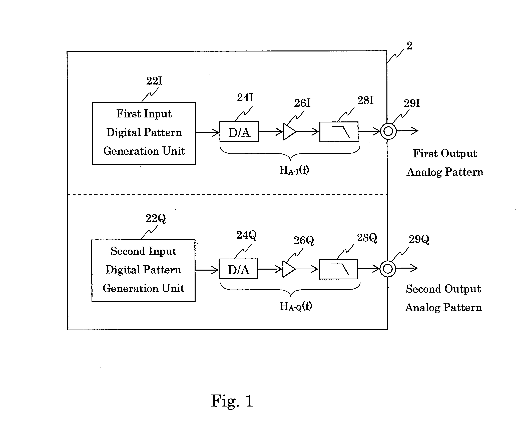
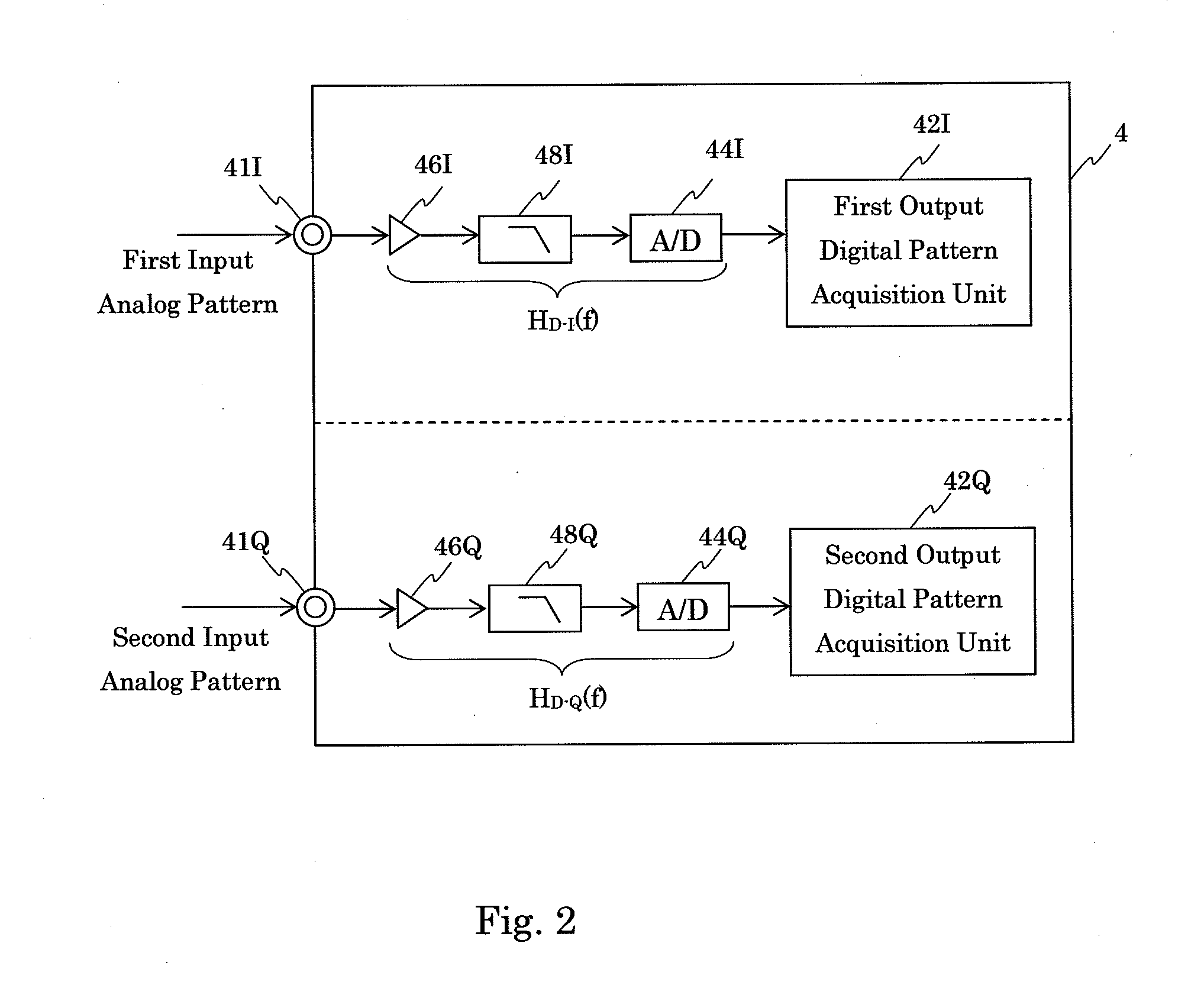
[0086]FIG. 3 is a block diagram showing a configuration of the characteristic acquisition device 1 according to a first embodiment. The characteristic acquisition device 1 according to the first embodiment is connected to the arbitrary waveform generator (analog pattern generation device) 2 and the digitizer (digital pattern acquisition device) 4. Moreover, the characteristic acquisition device 1 acquires a characteristic of the arbitrary waveform generator 2.
[0087]The characteristic acquisition device 1 according to the first embodiment includes a first transmission characteristic deriving unit 12, a second transmission characteristic deriving unit 14, a transmission characteristic ratio deriving unit 16 and a transmission characteristic deriving unit 18.
[0088]The first transmission characteristic deriving unit 12 operates when the first output terminal 29I and the first input terminal 41I are connected with each other. The first transmission characteristic deriving unit 12 receive...
second embodiment
[0115]FIG. 6 is a block diagram showing a configuration of the characteristic acquisition device 1 according a second embodiment. The characteristic acquisition device 1 according to the second embodiment is connected to the arbitrary waveform generator (analog pattern generation device) 2 and the digitizer (digital pattern acquisition device) 4. Moreover, the characteristic acquisition device 1 acquires a characteristic of the digitizer 4.
[0116]The characteristic acquisition device 1 according to the second embodiment includes a first transmission characteristic deriving unit 11, a second transmission characteristic deriving unit 13, a transmission characteristic ratio deriving unit 15 and a transmission characteristic deriving unit 17.
[0117]The first transmission characteristic deriving unit 11 operates when the first output terminal 29I and the first input terminal 41I are connected with each other. The first transmission characteristic deriving unit 11 receives the first input d...
third embodiment
[0144]FIG. 9 is a block diagram showing a configuration of the characteristic acquisition device 1 according to a third embodiment. The characteristic acquisition device 1 according to the third embodiment is connected to the arbitrary waveform generator (analog pattern generation device) 2 and the digitizer (digital pattern acquisition device) 4. Further, the characteristic acquisition device 1 acquires a delay characteristic on the transmission paths from the arbitrary waveform generator 2 to the digitizer 4.
[0145]The characteristic acquisition device 1 according to the third embodiment includes a first straight transmission characteristic deriving unit 102, a first cross transmission characteristic deriving unit 104, a second straight transmission characteristic deriving unit 106, a second cross transmission characteristic deriving unit 108, a delay characteristic deriving unit 110, a generation-side transmission characteristic ratio deriving unit 112, a generation-side transmiss...
PUM
 Abstract
Description
Claims
Application Information
 - R&D
- Intellectual Property
- Life Sciences
- Materials
- Tech Scout
- Unparalleled Data Quality
- Higher Quality Content
- 60% Fewer Hallucinations
Browse by: Latest US Patents, China's latest patents, Technical Efficacy Thesaurus, Application Domain, Technology Topic, Popular Technical Reports.
© 2025 PatSnap. All rights reserved.Legal|Privacy policy|Modern Slavery Act Transparency Statement|Sitemap|About US| Contact US: help@patsnap.com


