Drive control device for hybrid electric vehicle

a hybrid electric vehicle and control device technology, applied in the direction of electric devices, driver input parameters, external condition input parameters, etc., can solve the problems of disadvantageous fuel efficiency degradation, driver is incapable of recognizing running mode, driver may not properly depress the accelerator pedal, etc., to achieve the effect of improving fuel efficient running of the vehicl

Inactive Publication Date: 2011-01-27
DENSO CORP
View PDF13 Cites 74 Cited by
  • Summary
  • Abstract
  • Description
  • Claims
  • Application Information

AI Technical Summary

Benefits of technology

[0011]To achieve the objective of the present invention, there is provided a drive control device mounted to a hybrid electric vehicle that has an engine and a motor as a running power source, wherein the hybrid electric vehicle runs under a plurality of running modes that is switched in accordance with accelerator operation, wherein the drive control device performs a drive control of the engine and the motor, the drive control device including present position specifying means, accelerator operation schedule defining means, and display means. The present position specifying means specifies a present position of the vehicle. The accelerator operation schedule defining means defines a schedule of the accelerator operation for each of a plurality of sections in a route from an origin to a destination in order to achieve an enhanced fuel efficient running of the vehicle. The display means displays a recommended accelerator operation for a present section of the plurality of sections, in which section the vehicle is presently located, in accordance with the schedule of the accelerator operation and the present position of the vehicle.

Problems solved by technology

As a result, the fuel efficiency may deteriorate disadvantageously.
However, the driver is incapable of recognizing the running mode suitable for the enhanced fuel efficient running of the vehicle position in view of the entirety of the sections in the device of JP-A-2000-333305 disadvantageously, and thereby, for example, the driver may not depress the accelerator pedal properly.
As a result, the fuel efficiency may not be achieved as planned disadvantageously.

Method used


Image

  • Drive control device for hybrid electric vehicle
  • Drive control device for hybrid electric vehicle
  • Drive control device for hybrid electric vehicle

Examples


first embodiment

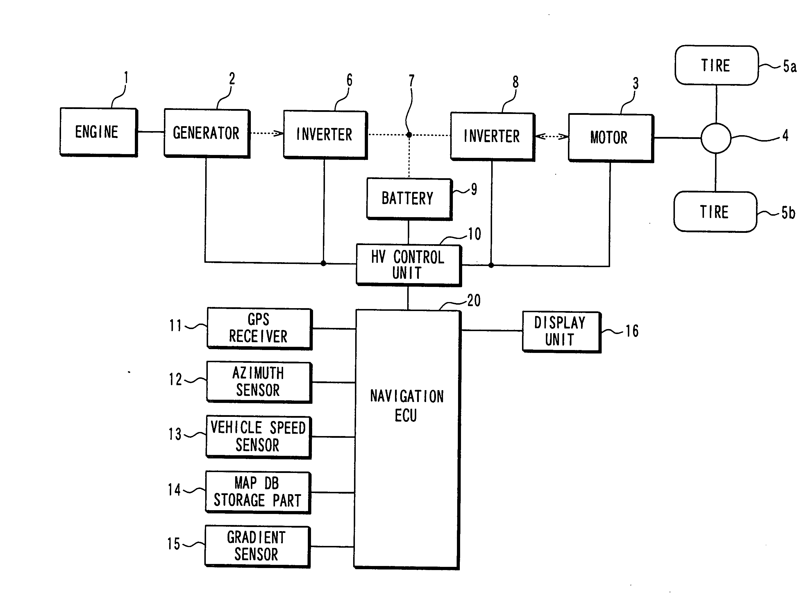
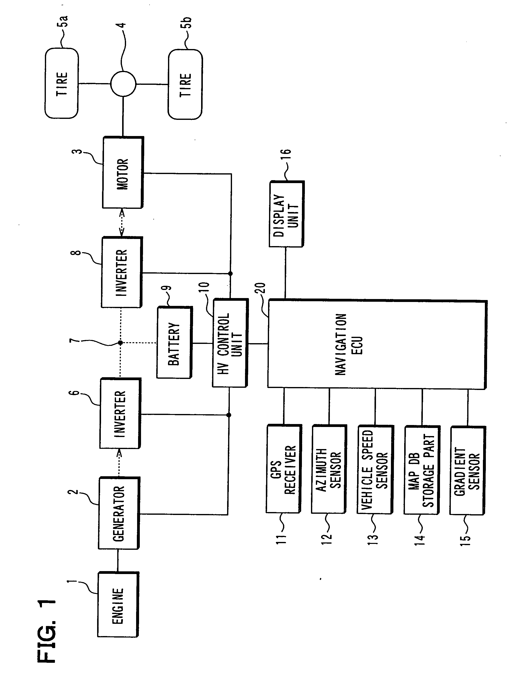
[0032]FIG. 1 schematically illustrates a general configuration of a vehicle mounted with a drive control apparatus for controlling a hybrid electric vehicle according to the first embodiment of the present invention. The hybrid electric vehicle is equipped with an engine 1 (internal combustion engine), a generator 2, a motor 3, a differential device 4, tires 5a, 5b, an inverter 6, a DC link 7, another inverter 8, a battery 9, an HV control unit 10, a GPS receiver 11, an azimuth sensor 12, a vehicle speed sensor 13, a map DB storage part 14, a gradient sensor 15, a display unit 16, and a navigation ECU 20.

[0033]The hybrid electric vehicle employs the engine 1 and the motor 3 as a power source for running, and runs under multiple running modes in accordance with accelerator pedal operation. When the engine 1 is used as the power source, a turning force of the engine 1 is transmitted to the tires 5a, 5b through clutch mechanism and the differential device 4, both of which are not shown...

second embodiment

[0095]FIGS. 12A to 12C illustrate display examples of the display unit 16 according to the second embodiment. FIG. 12A illustrates a map format of the schedule section (the road section 1 to 3), and FIGS. 12B and 12C illustrate the display examples of the indicator for each road section in the schedule section shown in FIG. 12A. In the first embodiment, as shown in FIGS. 11B and 11C, the accelerator pedal position of the vehicle is displayed in the following manner. The area (shaded part) indicating the accelerator pedal position is increased in proportion to the accelerator pedal position, and the range A, B of accelerator pedal position, which corresponds to the recommended running mode, flashes on and off at different positions on the indicator for different running modes. In the present embodiment, as shown in FIGS. 12B and 12C, the ranges A, B of accelerator pedal position, which correspond to the respective recommended running modes, are always displayed at respective predeter...

third embodiment

[0096]FIG. 13 is a schematic configuration that illustrates a vehicle mounted with a drive control device for a hybrid electric vehicle according to the third embodiment. The drive control device of the hybrid electric vehicle according to the present embodiment has a VICS receiver 17 in addition to the configuration shown in FIG. 1, and the VICS receiver 17 receives traffic jam information.

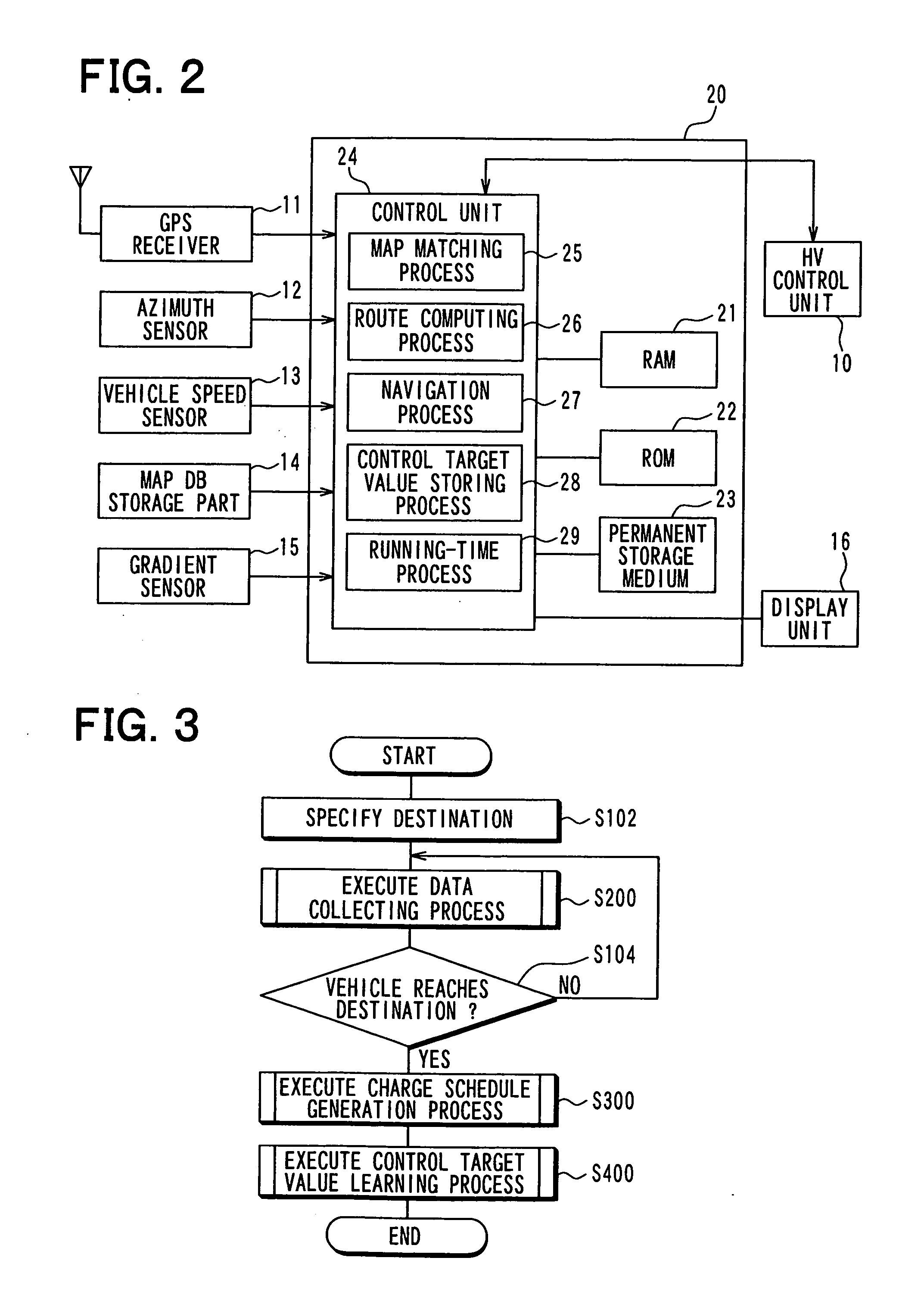
[0097]Also, the navigation ECU 20 of the present embodiment executes a traffic-jam-information-receiving-time process. More specifically, in the process, the navigation ECU 20 executes the control target value storing process 28 shown in FIG. 3. When the navigation ECU 20 determines that there is a traffic jam section ahead of the present position of the vehicle based on the traffic jam information received through the VICS receiver 17, the navigation ECU 20 displays the range of the accelerator pedal position, which enables the vehicle to run on the traffic jam section with the enhanced fuel eff...


PUM


Abstract

A drive control device is mounted to a hybrid electric vehicle that has an engine and a motor as a running power source, wherein the hybrid electric vehicle runs under a plurality of running modes that is switched in accordance with accelerator operation. The drive control device specifies a present position of the vehicle. The drive control device defines a schedule of the accelerator operation for each of a plurality of sections in a route from an origin to a destination in order to achieve an enhanced fuel efficient running of the vehicle. The drive control device displays a recommended accelerator operation for a present section of the plurality of sections, in which section the vehicle is presently located, in accordance with the schedule of the accelerator operation and the present position of the vehicle.

Description

CROSS REFERENCE TO RELATED APPLICATION[0001]This application is based on and incorporates herein by reference Japanese Patent Application No. 2009-171902 filed on Jul. 23, 2009.BACKGROUND OF THE INVENTION[0002]1. Field of the Invention[0003]The present invention relates to a drive control device mounted to a hybrid electric vehicle having an engine and a motor for a running power source, and the drive control device performs a drive control of the engine and the motor.[0004]2. Description of Related Art[0005]A conventional display device mounted to a hybrid electric vehicle causes a display unit to display an accelerator pedal position that changes with an operation amount of an accelerator pedal, and the display unit also displays a certain accelerator pedal position, at which a running mode is switched between an EV running (or motor running) mode and an HV running (or hybrid running) mode (see, for example, J P-A-2008-74321).[0006]Also, in a conventional drive control device of a...

Claims


Application Information

Patent Timeline
Patent Type & Authority Applications(United States)
IPC IPC(8): G06F19/00B60L50/16
CPCB60K6/46Y02T10/7291B60L11/126B60L11/1862B60L2210/40B60L2240/12B60L2240/622B60L2240/642B60L2240/68B60L2250/16B60L2260/46B60W10/06B60W10/08B60W10/26B60W20/102B60W30/1882B60W2530/14B60W2540/10B60W2550/142B60W2550/402Y02T10/56Y02T10/6217Y02T10/6291Y02T90/16Y02T90/162Y02T10/7077Y02T10/7044Y02T10/7005Y02T10/705Y02T10/7241B60L3/12B60W20/11Y02T10/84B60L50/62B60L58/13B60W2552/15B60W2556/50Y02T10/40Y02T10/62Y02T10/70Y02T10/72B60W2556/10B60W50/0097Y02T10/7072
Inventor YAMADA, KAZUNAOMIZUNO, YUSUKESAKAI, TADASHI
Owner DENSO CORP
Why Eureka
Try Eureka