
Cam adjustment module for compound archery bow

Active Publication Date: 2011-02-03
GRACE ENG
View PDF12 Cites 12 Cited by
  • Summary
  • Abstract
  • Description
  • Claims
  • Application Information

AI Technical Summary

Benefits of technology

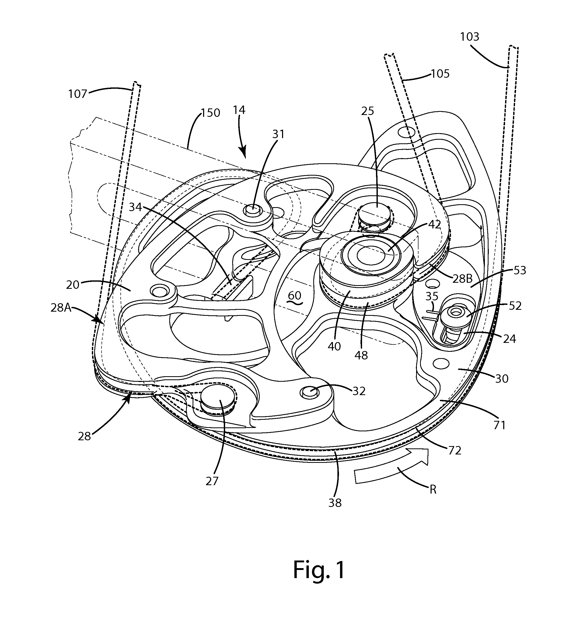
[0012]In one embodiment, the module includes a draw stop joined with it. The draw stop can be selectively moveable relative to the module, even while the adjustment module is attached to the cam, to adjust the draw stop to specific locations. Each location can correspond to a different amount of rotation of the cam, and thus the associated draw length and / or draw stop of the bow. The draw stop can effectively set a desired draw length and / or reduce the potential for overdrawing the bow, which can result in a hazardous situation for the archer.
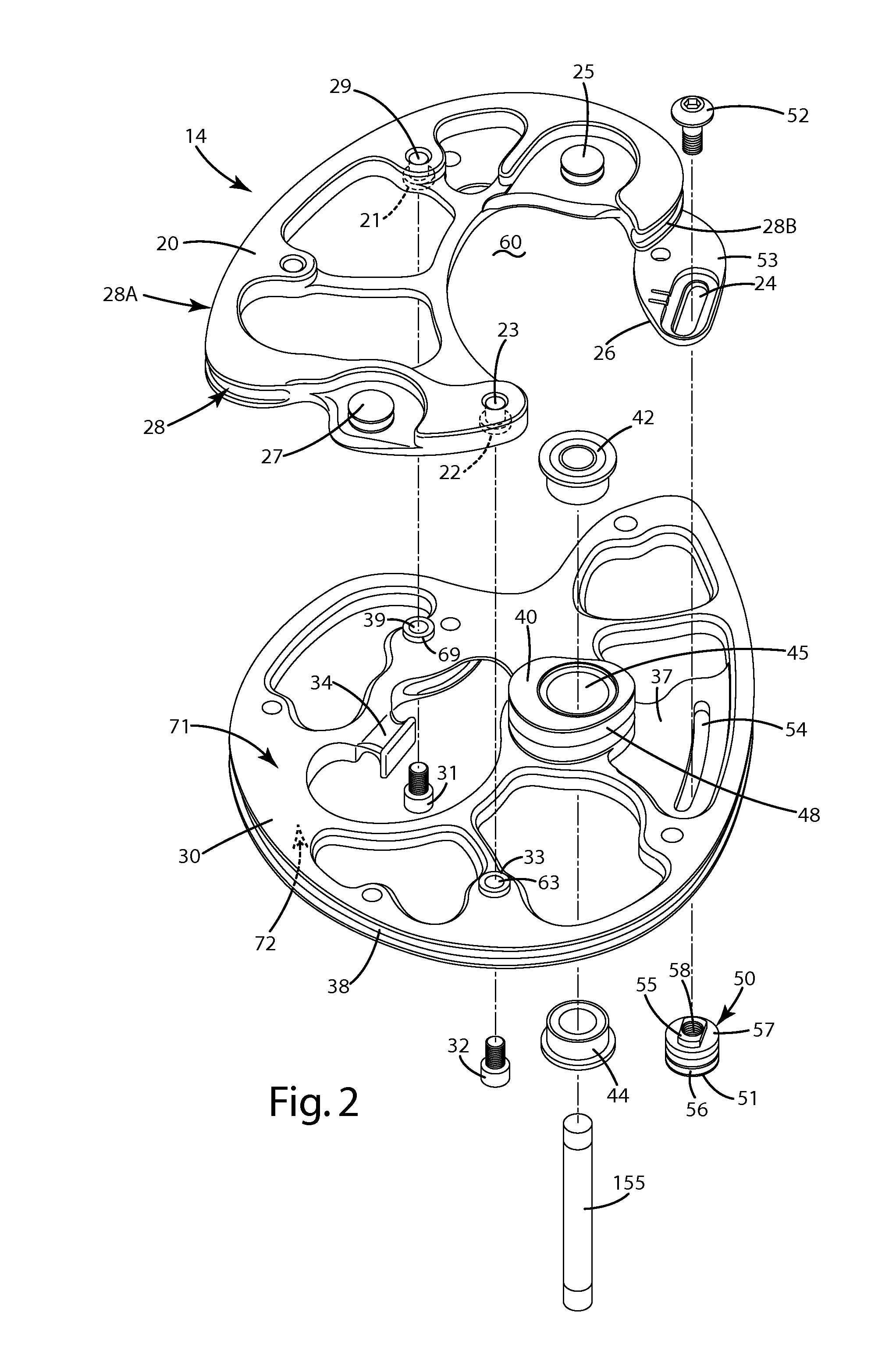
[0014]In yet another embodiment, the module of the cam system can include a recess that circumferentiates only a portion of an axle that joins the cam with a limb of the archery bow. Accordingly, the entire module can be removed from the cam, and optionally exchanged for another module having different performance characteristics, without having to remove the axle from the limb.
[0019]The cam system described herein provides a simple and efficient construction to facilitate precise adjustment of draw length, draw stop, draw force curve and / or other performance characteristics of the cam system or an associated archery bow. Where included, the draw stop is selectively moveable and can be adjusted to a variety of different locations to customize the draw stop for an archer. The indexing features, where included, provide accurate and precise registration between a module and a cam, which can provide a more finely-tuned cam system and prevent premature wear on components thereof. In addition, in cam systems where the module includes an axle recess, the module can be quickly removed and exchanged with another module if desired.

Problems solved by technology

The draw stop can effectively set a desired draw length and / or reduce the potential for overdrawing the bow, which can result in a hazardous situation for the archer.

Method used


Image

  • Cam adjustment module for compound archery bow
  • Cam adjustment module for compound archery bow
  • Cam adjustment module for compound archery bow

Examples


Embodiment Construction

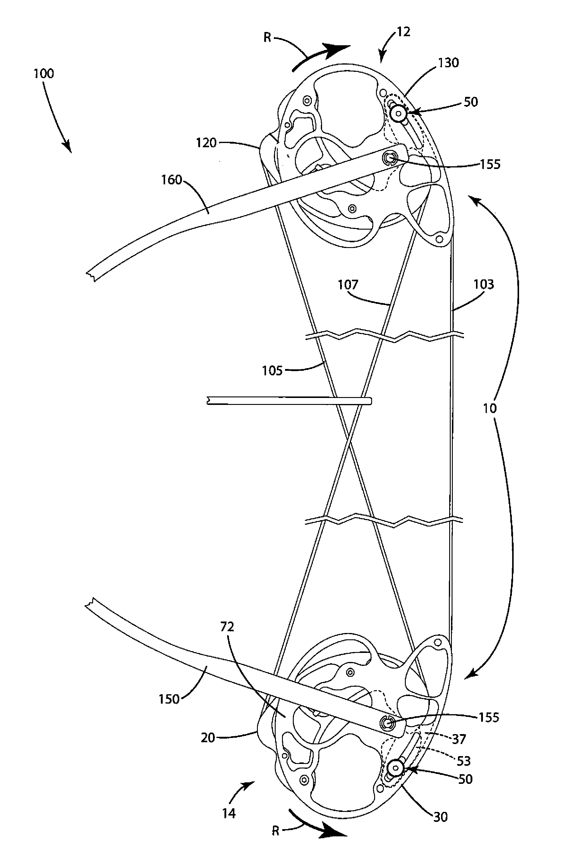
[0028]A cam system in accordance with a current embodiment is illustrated in FIGS. 1-7 and generally designated 10. This cam system 10 can include upper and lower cam assemblies 12 and 14 of a dual cam system on a bow 100, with the upper cam assembly 12 mounted to an upper limb 160 and the lower cam assembly 14 mounted to a lower limb 150 of a bow 100. In general, the lower and upper cam assemblies can include the same components, and can operate in a similar manner. Accordingly, only the lower cam assembly 14 will be described in significant detail herein, with the understanding that the upper cam assembly 12 can include the same components and can operate in a similar manner.

[0029]Although the current embodiment is described in connection with a dual cam system, the cam assemblies, adjustment modules, and other features are suited for use with more simple pulley systems, for example, in a single cam system. In such a system, for example, the lower cam assembly 14 can be paired wit...


PUM


Abstract

A cam system for an archery bow including a module that is readily attached to and detached from a cam while leaving the cam on the bow. The module can include a draw stop selectively moveable relative to the module, even while the module is joined with the cam, to adjust the draw stop to specific locations corresponding to different draw lengths and / or draw stop walls of the bow. The module can include a recess that surrounds only part of an axle joining the cam and bow so the entire module is removable from the cam without removing the axle. The cam system can include indexing features that precisely and consistently align features of the cam and module. These features can include first and second indexing posts, and corresponding indexing holes, that register with one another to precisely align the cam and module when joined.

Description

[0001]This application claims the benefit of U.S. Provisional Application 61 / 230,340, filed Jul. 31, 2009, which is hereby incorporated by reference.BACKGROUND OF THE INVENTION[0002]The present invention relates to compound archery bows, and more particularly to a cam system for a compound bow including an adjustment module.[0003]Conventional compound archery bows include a bowstring and a set of cables, usually an up cable and a down cable, to transfer energy from the limbs and cams or pulleys of the bow to the bowstring, and thus to an arrow shot from the bow. The cables and / or bowstring are strung from a cam or pulley on one limb to a cam or pulley on another limb. The function of the cam system is to provide a mechanical advantage so that energy imparted to the arrow is a multiple of that required of an archer to draw the bow.[0004]Most compound bows are outfitted with either single cam systems or dual cam systems, and are set-up to accommodate the specific draw length of the ar...

Claims


Application Information

Patent Timeline
IPC IPC(8): F41B5/10
CPCF41B5/105F41B5/10
Inventor GRACE, NATHANIEL E.
Owner GRACE ENG
Learn More