
Angle-selective irradiation insulation on a building envelope

a technology of irradiation insulation and building envelope, which is applied in the direction of solar heat devices, solar heat collector controllers, building components, etc., can solve the problems of building envelopes that are not suitable or limitedly effective for orientation, building envelope overheating, and high irradiation on the building, etc., to achieve easy, rapid and precise operation, and simple, efficient construction and manufacture.

Inactive Publication Date: 2014-07-17
SOLAR CAMPUS
View PDF0 Cites 3 Cited by
  • Summary
  • Abstract
  • Description
  • Claims
  • Application Information

AI Technical Summary

Benefits of technology

The invention provides a method for controlling the insulation of a building's envelope to match its specific needs and the orientation of the sun. This allows for better use of solar energy and protection against overheating. The method can also be used for artificial lighting and is easy to implement using a computer program. The technical effects include improved energy efficiency and better control over the building's temperature.

Problems solved by technology

As a result, the known building envelopes of building envelope parts are either unsuitable or limitedly effective for orientations that deviate from the south, for inclined or horizontal configurations, for example roof surfaces, as well as for other geographic latitudes.
As a consequence, the irradiation on the building is often very high when the building exhibits such a known building envelope, and the amount of irradiated energy is often significant given the longer duration of sunshine in the mornings and evenings, and can help cause the building to overheat.

Method used


Image

  • Angle-selective irradiation insulation on a building envelope
  • Angle-selective irradiation insulation on a building envelope
  • Angle-selective irradiation insulation on a building envelope

Examples


Embodiment Construction

[0008]According to the invention, the object is achieved by a building envelope part as defined by the features in independent claim 1, as well as by a method as defined by the features in independent claim 10, and a computer program as defined by the features in independent claim 18. Advantageous embodiments of the invention may be gleaned from the features in the dependent claims.

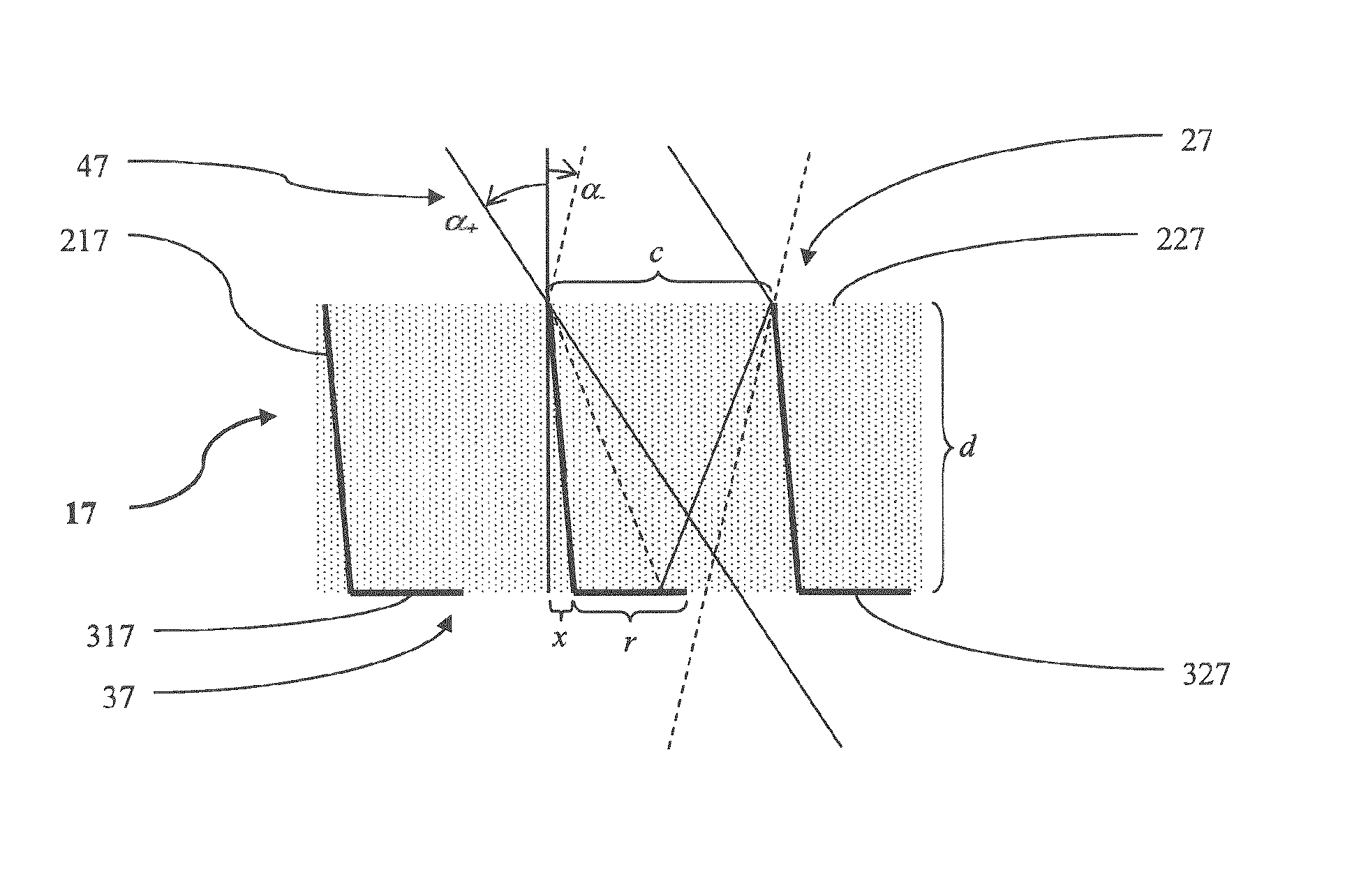
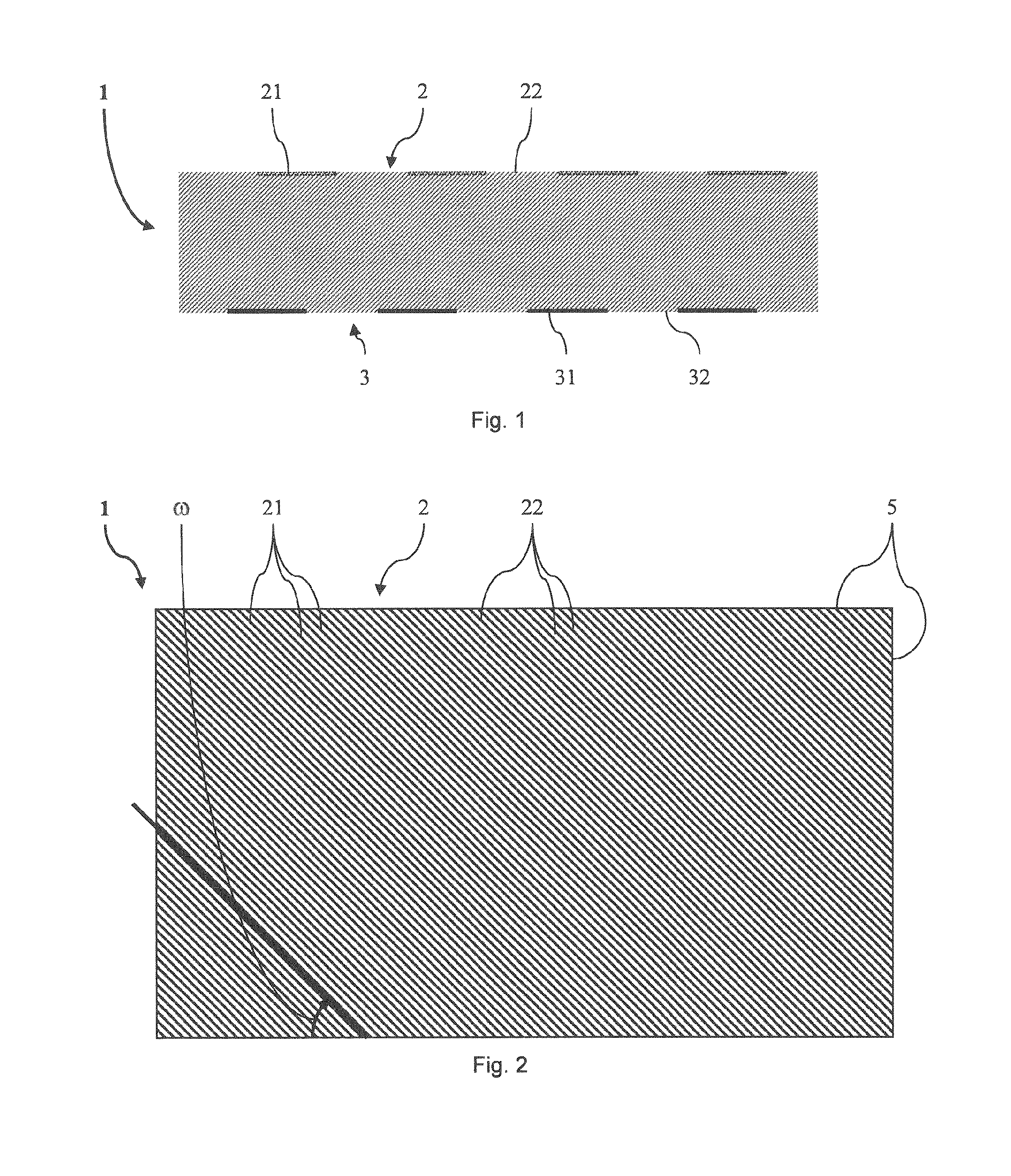
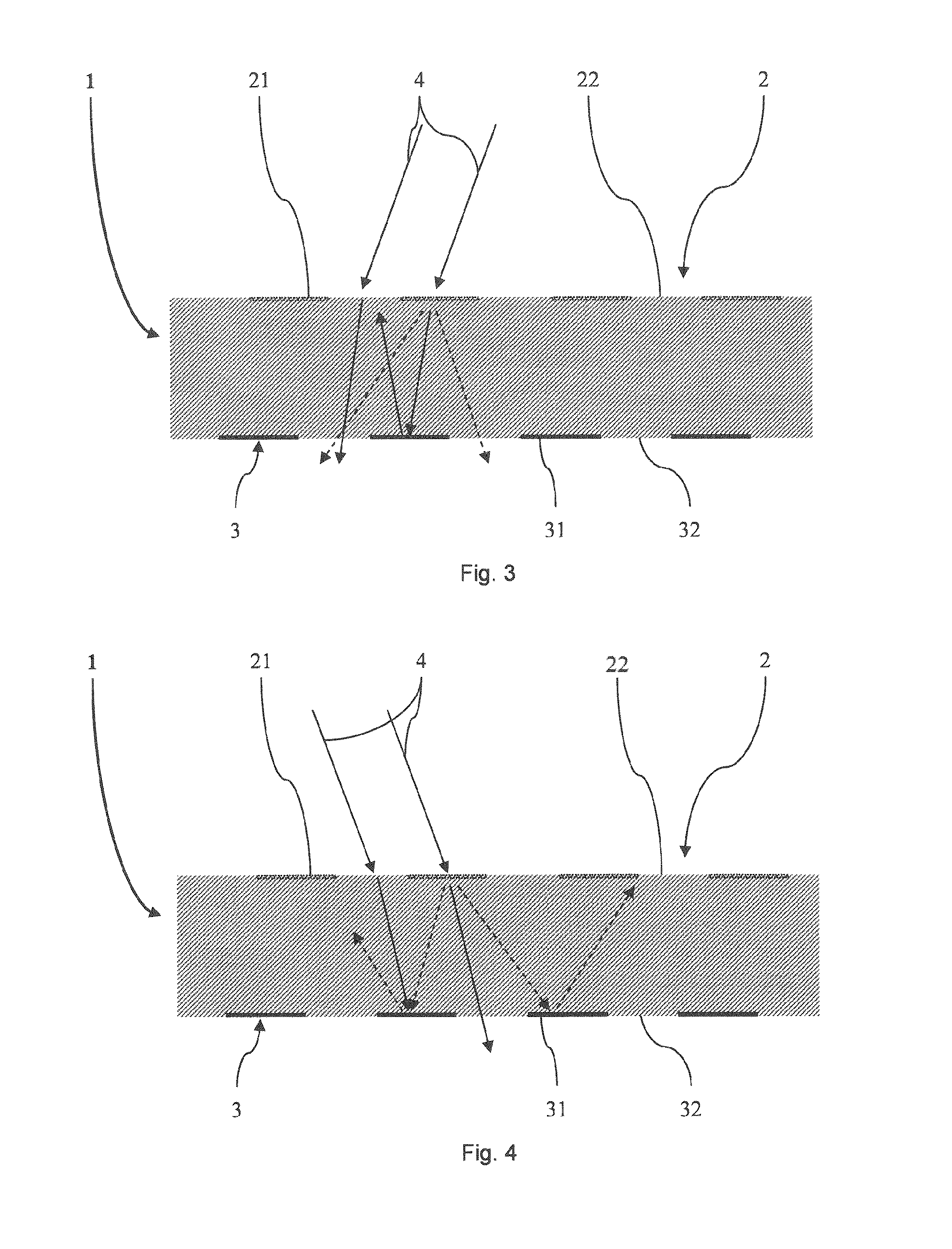
[0009]The gist of the invention is as follows: A building envelope part for angle-selective irradiation insulation on a building envelope exhibits an outer surface with outer structures, an inner surface opposite the outer surface with inner structures, and a side edge that borders the outer surface and inner surface, or joins the outer surface with the inner surface. The outer structures and inner structures are here arranged relative to each other in such a way that the translucency of the building envelope part varies as a function of the spatial angle of incidence. The outer structures and inner struc...


PUM

PropertyMeasurementUnit
azimuth anglesaaaaaaaaaa

Abstract

In a method for producing a building envelope part (19) for angle-selective irradiation insulation on a building envelope, which building envelope part (19) has an outer surface (29), an inner surface (39) opposite the outer surface (29), and a side edge that bounds the outer surface (29) and the inner surface (39), the outer surface (29) is provided with outer structures (219) and the inner surface (39) is provided with inner structures (319). The outer structures (219) and the inner structures (319) are arranged relative to each other in such a way that the building envelope part (19) has different transparency depending on the spatial angle of incidence. The outer structures (219) and the inner structures (319) are arranged in particular with regard to an orientation of an intended application of the building envelope part (19) and with regard to the latitude of the intended application of the building envelope part (19). By means of the design of the outer structures and the inner structures according to the invention, it is possible that the outer structures and the inner structures are arranged in such a way that a building envelope comprising the building envelope part is optimally adapted to an orientation and in particular to an orientation deviating from southern orientation, to tilted or horizontal arrangements, or to an arbitrary latitude. Thus the transmittance behavior of the building envelope part can be accordingly optimized for the particular situation.

Description

BENEFIT CLAIM[0001]The present application claims the benefit under 35 U.S.C. 119 of priority from international application PCT / EP2012 / 061835 filed 20 Jun. 2012, which claims priority to European application EP11170686.7 filed 21 Jun. 2011, the entire contents of which are hereby incorporated by reference for all purposes as if fully set forth herein.TECHNICAL FIELD[0002]The invention relates to a building envelope part according to the preamble of independent claim 1, as well as to a method for manufacturing such a building envelope and a computer program for implementing such a method.[0003]Such building envelope parts exhibit an outer surface with outer structures, an inner surface opposite the outer surface with inner structures, and a side edge that bounds the outer surface and inner surface, wherein the outer structures and inner structures are arranged relative to each other in such a way that the building envelope part has a varying translucency depending on the spatial ang...

Claims


Application Information

Patent Timeline
Patent Type & Authority Applications(United States)
IPC IPC(8): E04B1/62
CPCE04B1/62E06B3/6722F24J2/407F24S50/80
Inventor MATHEZ, STEPHAN A.SACHS, WALTER
Owner SOLAR CAMPUS
Learn More