Plate Heat Exchanger

a heat exchanger and plate technology, applied in the direction of heat exchanger fastening, lighting and heating apparatus, reinforcement means, etc., can solve the problems of merely being moved, not improving the strength at another area of the plate heat exchanger, and difficult to achieve high design pressure, etc., to achieve high strength and high strength of the plate package

Inactive Publication Date: 2011-02-03
ALFA LAVAL CORP AB
View PDF6 Cites 8 Cited by
  • Summary
  • Abstract
  • Description
  • Claims
  • Application Information

AI Technical Summary

Benefits of technology

[0009]According to a further embodiment of the invention, also the inner portions of each porthole area are distributed with an equal inner angular distance between adjacent inner portions. Also suc

Problems solved by technology

Such high design pressures are difficult to achieve without the provision of external strengthening components.
However, although a certain design of the porthole areas w

Method used


Image

  • Plate Heat Exchanger
  • Plate Heat Exchanger
  • Plate Heat Exchanger

Examples


Embodiment Construction

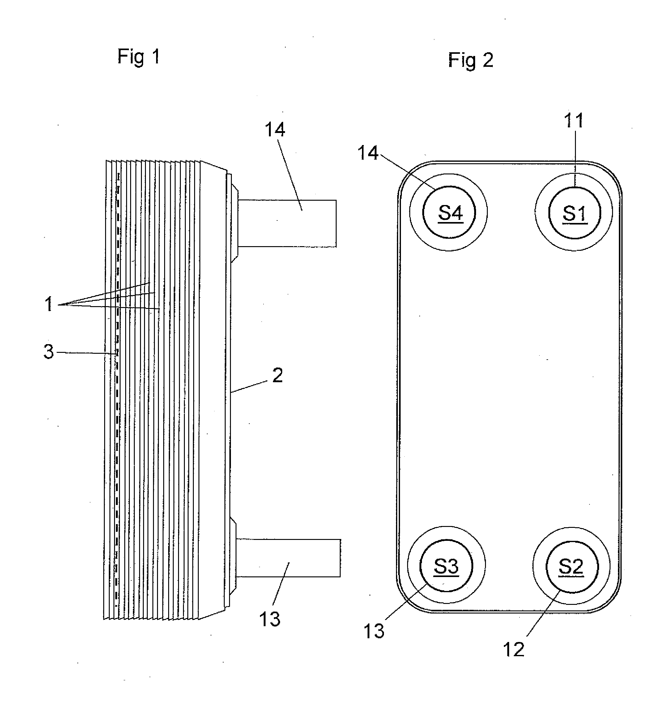
[0025]FIGS. 1 and 2 shows a plate heat exchanger comprising a plurality of heat exchanger plates 1, a first end plate 2, which is provided beside an outermost one of the heat exchanger plates 1, and a second end plate 3, which is provided beside the other opposite outermost heat exchanger plate 1.

[0026]The heat exchanger plates 1 are produced through forming of a metal sheet and provided beside each other. The first end plate 2, the second end plate 3 and the heat exchanger plates 1 are permanently joined to each other through brazing by means of a braze material to form a plate package. The plate package define or have first plate interspaces 4 for a first medium and second plate interspaces 5 for a second medium, see FIG. 6. The first and second medium may be any suitable heat transfer medium. For instance, the first and / or the second medium may be carbon dioxide.

[0027]The plate heat exchanger of the embodiments disclosed has four portholes S1, S2, S3 and S4, wherein the porthole ...


PUM


Abstract

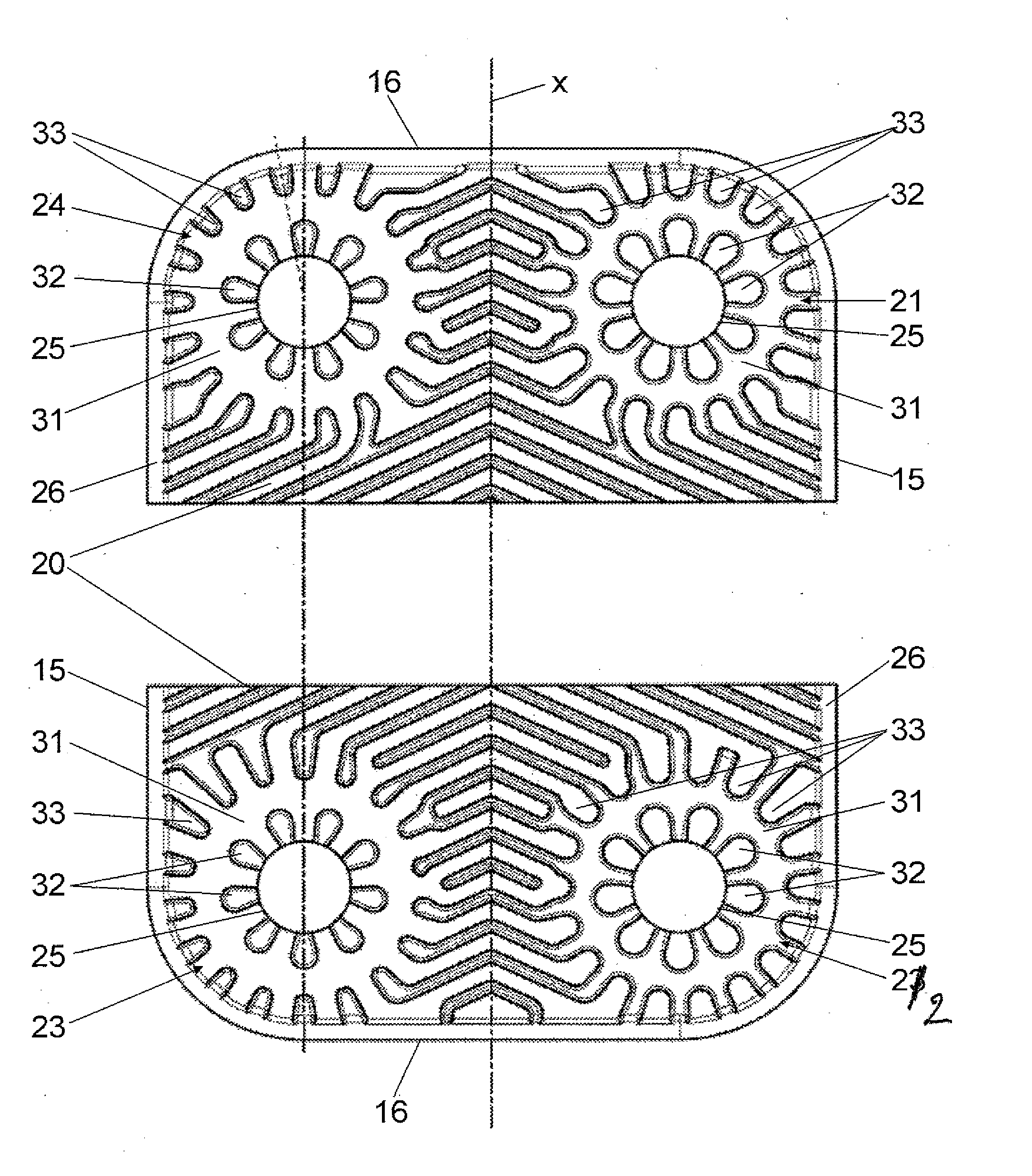
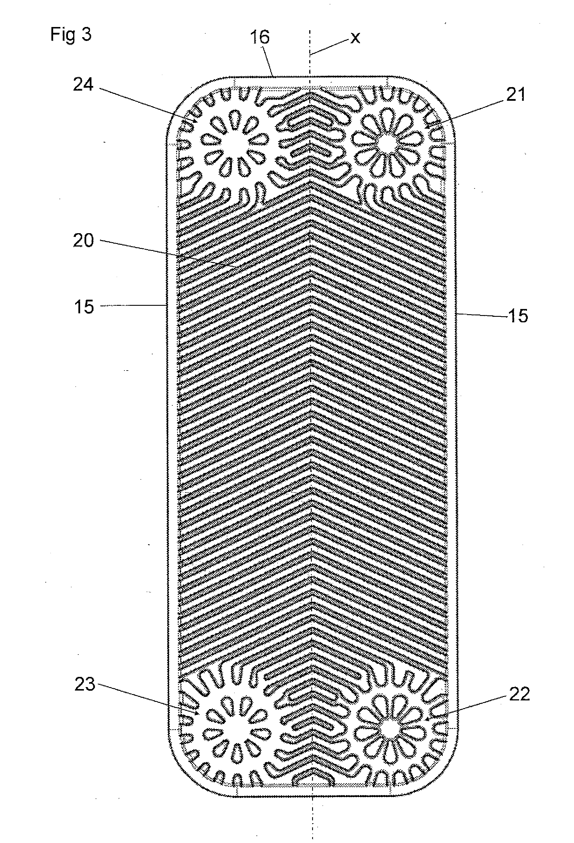
A plate heat exchanger comprises a plurality of heat exchanger plates joined to each other. Each plate (1) has a heat transfer area (20), a first porthole area (21), a second porthole area (22), a third porthole area (23) and a fourth porthole area (24). Each porthole area surrounds a porthole having a porthole edge (25). Each porthole area comprises an annular flat area (31), a set of inner portions (32) on the annular flat area along the porthole edge (25), and a set of outer portions (33) along the annular flat area (31) at a distance from the inner portions. The outer portions of the first porthole area have a first relative peripheral position with respect to the inner portions. The outer portions of the fourth porthole area have a second relative peripheral position with respect to the inner portions. The first relative peripheral position includes a peripheral displacement in relation to the second relative peripheral position.

Description

THE FIELD OF THE INVENTION[0001]The present invention refers to a plate heat exchanger according to the preamble of claim 1.[0002]In many heat exchanger applications, it is desirable to achieve a high, or a very high, design pressure, i.e. to be able to permit a high or a very high pressure of one or both of the media flowing through the plate interspaces. It is also desirable to be able to permit such high pressures in plate heat exchangers of the kind defined above having permanently joined heat exchanger plates, e.g. through brazing. Such high design pressures are difficult to achieve without the provision of external strengthening components.[0003]A weak area in such plate heat exchangers is the porthole area, i.e. the area immediately around the portholes. These areas determine the design pressure in plate heat exchangers used today. However, although a certain design of the porthole areas would improve the design pressure, this design would not improve the strength at another ...

Claims


Application Information

Patent Timeline
IPC IPC(8): F28F3/08
CPCF28D9/005F28F2225/04F28F2275/04F28F3/046
Inventor CHRISTENSEN, ROLFANDREASSON, FREDRIKBERMHULT, ROLFLARSSON, HAKANSVENSSON, MAGNUS
Owner ALFA LAVAL CORP AB
Why Eureka
Try Eureka