Level sensors for metering system container

Inactive Publication Date: 2011-02-03
CNH IND AMERICA LLC
View PDF21 Cites 0 Cited by
  • Summary
  • Abstract
  • Description
  • Claims
  • Application Information

AI Technical Summary

Benefits of technology

[0006]The present invention provides sensor assemblies that may be placed within the metering system storage container and configured to determine material level despite dusty or damp conditions. In an exemplary embodiment, a first sensor assembly is positioned within a lower portion of the container and configured to indicate a low material level in the container based on physical contact with the material. In addition, a second sensor assembly is positioned within an upper portion of the container and configured to indicate a substantially full material level in the container based on physical contact with the material. A controller is communicatively coupled to the first and second sensor assemblies and configured to engage a transfer of material to the container in response to the low material level indication from the first sensor assembly and to disengage the transfer of material to the container in response to the substantially full material level indication from the second sensor assembly. Because the sensor assemblies operate based on physical contact with the material, material level within the storage container may be maintained despite dusty or damp conditions. Therefore, a proper supply of material is provided to a delivery system, thereby resulting in a substantially even distribution of material across a field.

Problems solved by technology

Because conventional float switches are not particularly effective in such arrangements, top loaded metering systems typically employ a photoelectric sensor configured to optically observe the level of material within the storage container.
However, photoelectric sensors will not function properly if dust from the material obscures the optical measurement.
Similarly, damp material may adhere to the sensor, thereby blocking visual observation of the material level within the storage container.
At that point, the metering system may exhaust its supply of material, thereby resulting in uneven distribution of material across the field.

Method used


Image

  • Level sensors for metering system container
  • Level sensors for metering system container
  • Level sensors for metering system container

Examples


Embodiment Construction

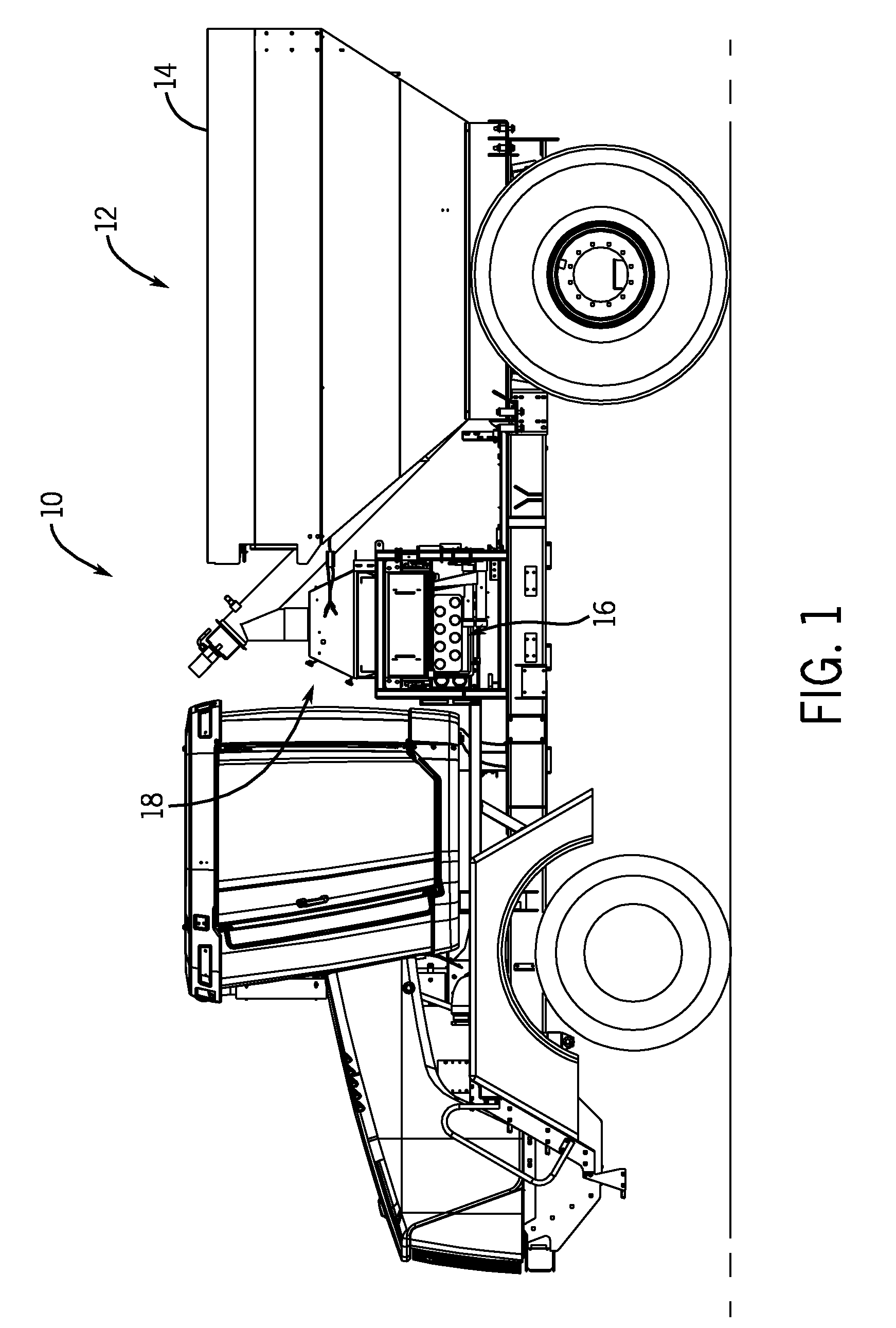
[0012]FIG. 1 is a perspective view of an applicator vehicle 10 including a material distribution system 12. The material distribution system 12 is configured to deliver a dry fertilizer and / or granular herbicide to a field. Specifically, the material distribution system 12 includes a material holding bin 14, a delivery system 16 and a metering system 18. The material holding bin 14 is configured to store material (e.g., fertilizer, herbicide, etc.) for distribution. Material from the material holding bin 14 is conveyed to the metering system 18 by a device capable of transferring dry material (e.g., an auger). The metering system 18 then transfers measured amounts of material to the delivery system 16. Certain delivery systems 16 include booms that extend laterally outward from each side of the applicator vehicle 10. The delivery system 16 receives measured amounts of material from the metering system 18 and dispenses the material onto the soil.

[0013]As discussed in detail below, th...


PUM


Abstract

Level sensors for a metering system container are provided that facilitate determining material level within the container despite dusty or damp conditions. In an exemplary embodiment, a material metering system includes a first sensor assembly disposed within a lower portion of the container and a second sensor assembly disposed within an upper portion of the container. Each sensor assembly is configured to output a signal indicative of contact with the material. The material metering system also includes a controller communicatively coupled to the first and second sensor assemblies and configured to engage a transfer of material to the container in response to the signal from the first sensor assembly indicative of contact with the material and to disengage the transfer of material to the container in response to the signal from the second sensor assembly indicative of contact with the material.

Description

BACKGROUND[0001]The invention relates generally to level sensors for a metering system container, and more specifically, to a pair of sensors configured to physically contact material within the metering system container to control a flow of material into the container.[0002]In agricultural settings, various types of applicators are employed to deliver liquid or dry fertilizer and / or herbicide to the surface of a field. In a typical configuration, applicators include a material distribution system mounted on a vehicle. The material distribution system is configured to store, meter, and distribute fertilizer and / or herbicide to the field. For example, a material distribution system configured to distribute dry fertilizer generally includes a material holding bin for storing the fertilizer. The material distribution system also includes a metering system configured to receive material from the material holding bin and transfer specific quantities of material to a delivery system. The ...

Claims


Application Information

Patent Timeline
IPC IPC(8): B67D5/08
CPCA01C7/105G05D9/12A01C15/006
Inventor ELLINGSON, JONLAGRED, EDWALTON, JERRY
Owner CNH IND AMERICA LLC
Why Eureka
Try Eureka