Electrical power generation apparatus for contra-rotating open-rotor aircraft propulsion system

a technology of electric power generation apparatus and contra-rotating open-rotor aircraft, which is applied in the direction of efficient propulsion technology, machines/engines, transportation and packaging, etc., can solve the problems of affecting the flight safety of aircra

Active Publication Date: 2011-02-03
ROLLS ROYCE NORTH AMERICAN TECH
View PDF42 Cites 67 Cited by
  • Summary
  • Abstract
  • Description
  • Claims
  • Application Information

AI Technical Summary

Benefits of technology

[0009]The present invention thereby provides electrical power to rotating parts of a contra-rotating mechanical system w...

Problems solved by technology

Icing of aerodynamic surfaces is a well-known problem in the art of aeronautics.
However, with particular reference to open rotor aircraft propulsion systems, on-ground treatments have not proven generally effective for the duration of flight.
There are several difficulties with the various known methods for transferring power from the main airframe to the rotors of a contra-rotating open rotor aircraft propulsion system.
Mechanical power transfer requires rotating contact between components that wear, bind, slip, and/or add undesirable weight and/or friction to the propulsion rotor assembly.
Optical beam power transfer is susceptible to interference from opaque materials, and typically requires a fixed line-of-sight not easily achieved in a contra-rotating propulsion rotor system.
Fluid power transfer along a contra-rotating propulsion rotor system requires provision of complex ...

Method used


Image

  • Electrical power generation apparatus for contra-rotating open-rotor aircraft propulsion system
  • Electrical power generation apparatus for contra-rotating open-rotor aircraft propulsion system
  • Electrical power generation apparatus for contra-rotating open-rotor aircraft propulsion system

Examples


Embodiment Construction

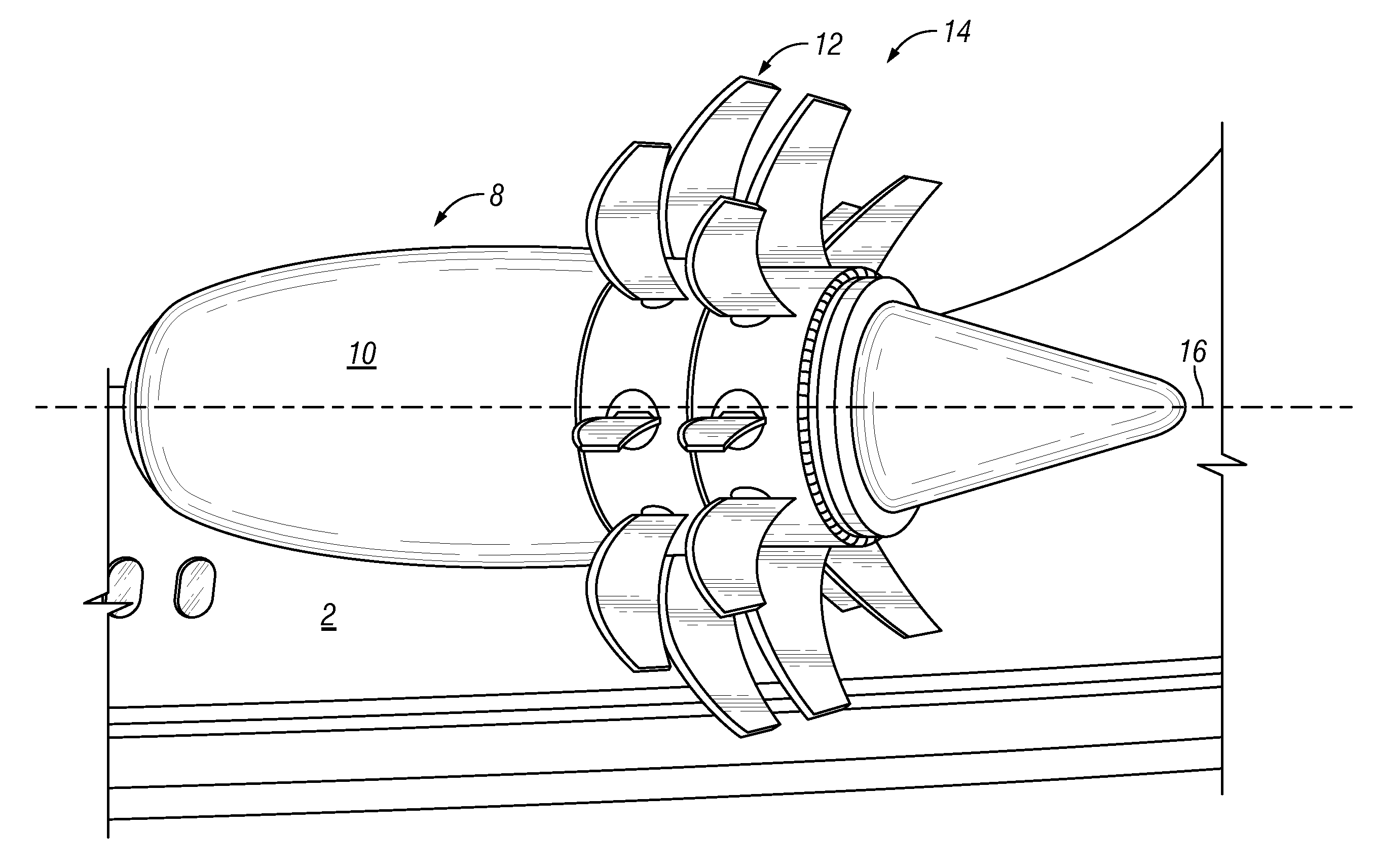
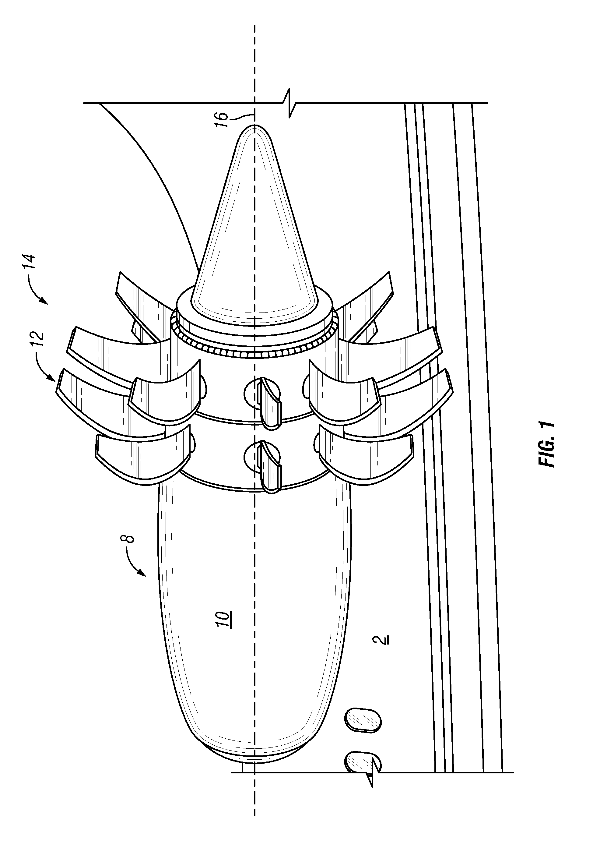
[0019]Referring to FIG. 1, a jet aircraft 2 can be propelled by a contra-rotating open rotor propulsion system 8, which is controlled by an avionics package (not shown). The contra-rotating open rotor propulsion system 8 includes a jet engine 10 or similar prime mover, which drives a forward open rotor blade set 12 and an aft open rotor blade set 14 disposed aft of the jet engine in a “pusher configuration”. Alternatively, the forward and aft rotor blade sets can be disposed forward of the jet engine in a “tractor configuration”. Throughout the following detailed description of the drawings, the forward rotor blade set should be regarded as exemplary of a rotor blade set disposed proximate to the jet engine, and the aft rotor blade set should be regarded as exemplary of a rotor blade set disposed distal from the jet engine. The forward and aft rotor blade sets contra-rotate about a common axis 16 defined by the jet engine. For example, the forward shaft can be driven by the jet engi...


PUM


Abstract

An electrical power generation apparatus is embedded in a contra-rotating propulsion system that includes overlapping first and second shafts operatively connected for counter-rotation about a common axis. The electrical power generation apparatus includes a winding mounted to one of the shafts and a field array mounted to the other of the shafts adjacent to the winding. Relative rotation of the winding and the field array induces electrical current in the winding.

Description

CROSS REFERENCE TO RELATED APPLICATIONS[0001]This application is a continuation-in-part of, and claims priority to, U.S. patent application Ser. No. 12 / 510,334, filed on Jul. 28, 2009, hereby incorporated herein by reference in its entirety.FIELD OF THE INVENTION[0002]The present invention relates generally to apparatus for de-icing rotors of aircraft propulsion systems, and more particularly to an electrical power generation apparatus for providing electrical power to de-icing apparatus mounted on rotors of a contra-rotating open rotor aircraft propulsion system.BACKGROUND OF THE INVENTION[0003]Icing of aerodynamic surfaces is a well-known problem in the art of aeronautics. Icing can be partly mitigated by on-ground application of chemical compounds to prevent formation or adhesion of ice particles on the aerodynamic surfaces. However, with particular reference to open rotor aircraft propulsion systems, on-ground treatments have not proven generally effective for the duration of fl...

Claims


Application Information

Patent Timeline
IPC IPC(8): B64D15/12H02K23/60H02K9/19H02K9/02
CPCB64C11/48B64D15/12B64D2027/005B64D2027/026F05D2220/768H02K7/1823Y02T50/66Y02T50/671F02K3/072Y02T50/60
Inventor BLACKWELDER, MARK J.ALT, JOHN TIMOTHYGAGNE, STEVENVETTERS, DANIEL KENT
Owner ROLLS ROYCE NORTH AMERICAN TECH
Why Eureka
Try Eureka