Lensed optical connector with passive alignment features

Inactive Publication Date: 2011-02-03
IBM CORP
View PDF19 Cites 57 Cited by
  • Summary
  • Abstract
  • Description
  • Claims
  • Application Information

AI Technical Summary

Benefits of technology

[0008]Accordingly, it is an object of the present invention to provide a novel and advantageous connector for fiber or waveguide cables with arrays of microlenses in a structure which incorporate passive guiding features ensuring an accurate optically aligned communication between these components.
[0009]A more specific object of the present inventio

Problems solved by technology

Although the connected structure discloses a solution to various problems that are encountered by fiber connectors, such as loss of accuracy, it does not incorporate any optical microlenses which are intended to be mated in a precise manner with an array of the optical fibers, and also fails to disclose the manner in which a stack of waveguides is aligned to anothe

Method used


Image

  • Lensed optical connector with passive alignment features
  • Lensed optical connector with passive alignment features
  • Lensed optical connector with passive alignment features

Examples


Embodiment Construction

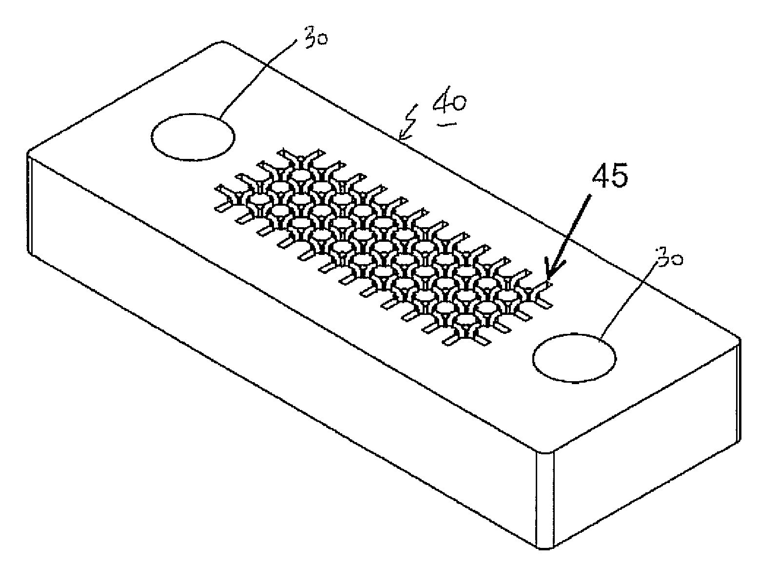
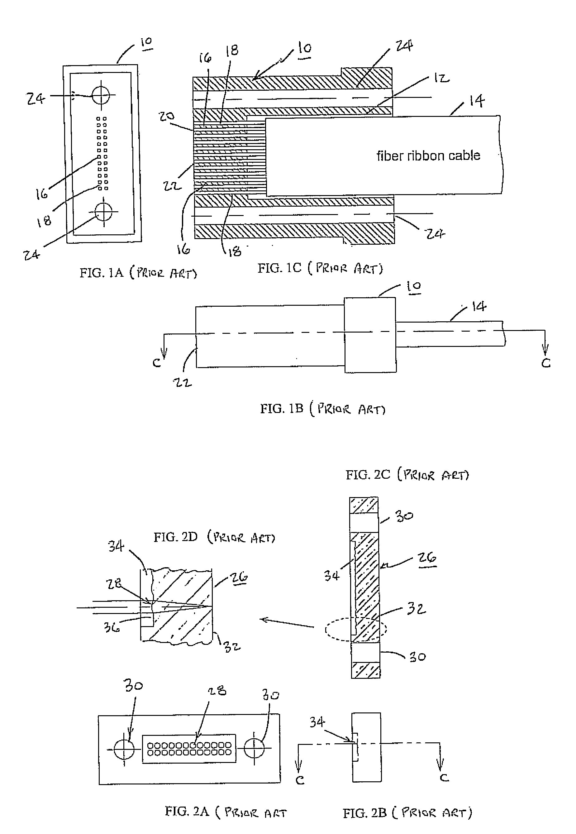
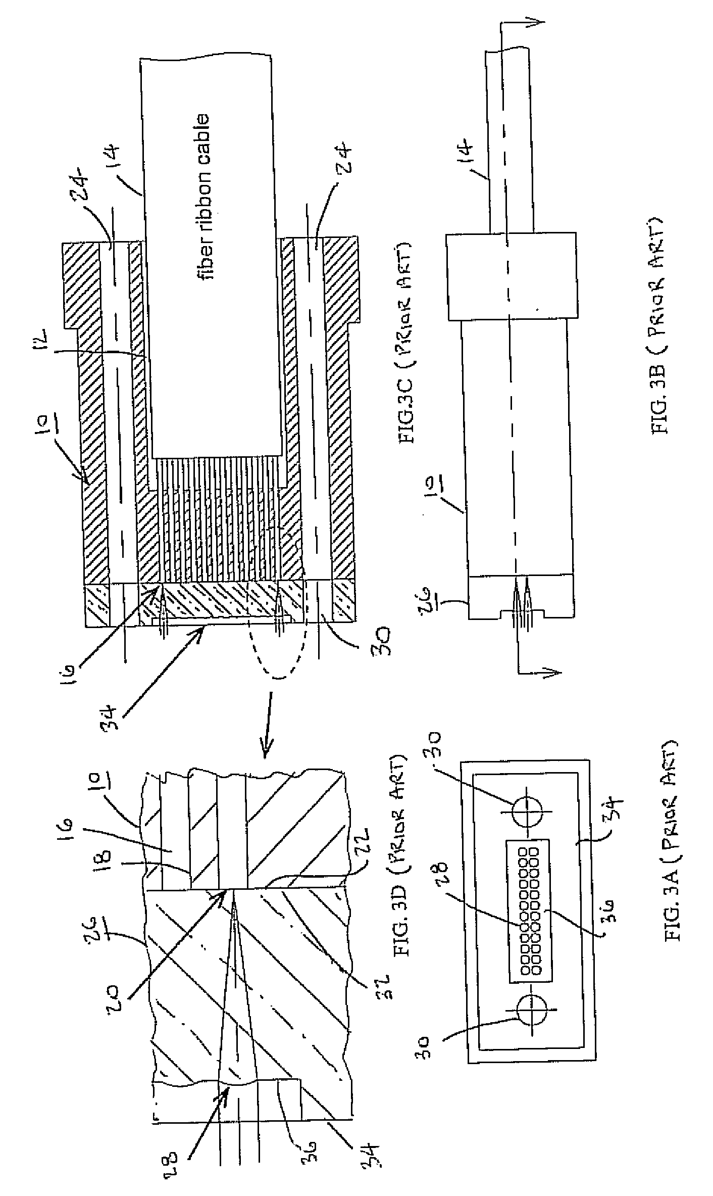
[0018]Referring now in detail to the drawings, in particular the prior art embodiment representation of FIGS. 1A-1C, there is disclosed a simple ferrule 10 having an aperture 12 for the receipt of a fiber ribbon cable 14. The cable 14 includes a 3-dimensional array of optical fibers 16 extending forwardly from the cable 14 through small holes 18 in the ferrule communicating with aperture 12, so as to terminate in polished fiber ends 20 coextensive with the front surface 22 of the ferrule. The ferrule holes 18 form close-fitting guide holes for the respective optical fibers 16 and whereby the polished front ends of the fibers are intended to be aligned with optical lenses as detailed hereinbelow. The ferrule also contains at least two guide holes 24 adapted to be aligned with similar guide holes in a microlens-containing member, and for receiving suitable connectors (not shown.).

[0019]Concerning the foregoing, the holes 18 which guide the respective optical fibers 16 towards the lead...


PUM


Abstract

A simply constructed and economical optical connector, wherein a fiber ribbon or waveguide ribbon cable incorporates a plurality of projecting fiber or waveguide ends adapted to engage into a guiding feature in a structure that incorporates an array of microlenses, upon said structure being aligned with and attached to a ferrule housing the ribbon cable. The guiding feature enables apertures in the ferrule within which the projecting fiber or waveguide ends are guides towards engagement with guiding feature in the microlens containing structure, to be formed or dimensioned with relaxed tolerances relative to the fiber or waveguide ends, thereby considerable reducing manufacturing costs for the ferrule.

Description

FIELD OF THE INVENTION[0001]The present invention relates to a lens optical connector possessing passive alignment features, and more particularly pertains to a self-aligning optical interconnect structure for the connection of the fiber ends or optical wave guides to arrays of microlenses.[0002]In the technological field of data processing and architecturally larger multi-core processing system arrangements there is an ever-increasing need for high speed optical interconnects with the utilization of optical fiber arrays.[0003]With respect to the foregoing, it has become readily evident in the technology that the employment of optical waveguides will provide an efficient and economical method of managing the employment of large numbers of optical channels, wherein in particular, there is a present need for the provision of structurally simple, low cost waveguide connectorizations which are not bound to precise waveguide thickness controls. In that connection, the use of novel optica...

Claims


Application Information

Patent Timeline
IPC IPC(8): G02B6/42G02B6/36G02B6/38
CPCG02B6/32G02B6/4249G02B6/4204G02B6/3885
Inventor BUDD, RUSSELL A.LIBSCH, FRANK R.
Owner IBM CORP
Why Eureka
Try Eureka