Optical module

a technology of optical fiber and optical fiber, applied in the field of optical fiber modules, can solve the problems of restricted movement of the tray and excessive load on the optical fiber, and achieve the effect of preventing the damage of the optical fiber

Active Publication Date: 2011-02-03
LUMENTUM JAPAN INC
View PDF6 Cites 19 Cited by
  • Summary
  • Abstract
  • Description
  • Claims
  • Application Information

AI Technical Summary

Benefits of technology

[0007]Therefore, it is an object of the present invention to prevent an optical fiber from being damaged.

Problems solved by technology

In addition, movement of the tray is restricted, and hence excessive load is not applied to the optical fiber.

Method used


Image

  • Optical module
  • Optical module
  • Optical module

Examples


first embodiment

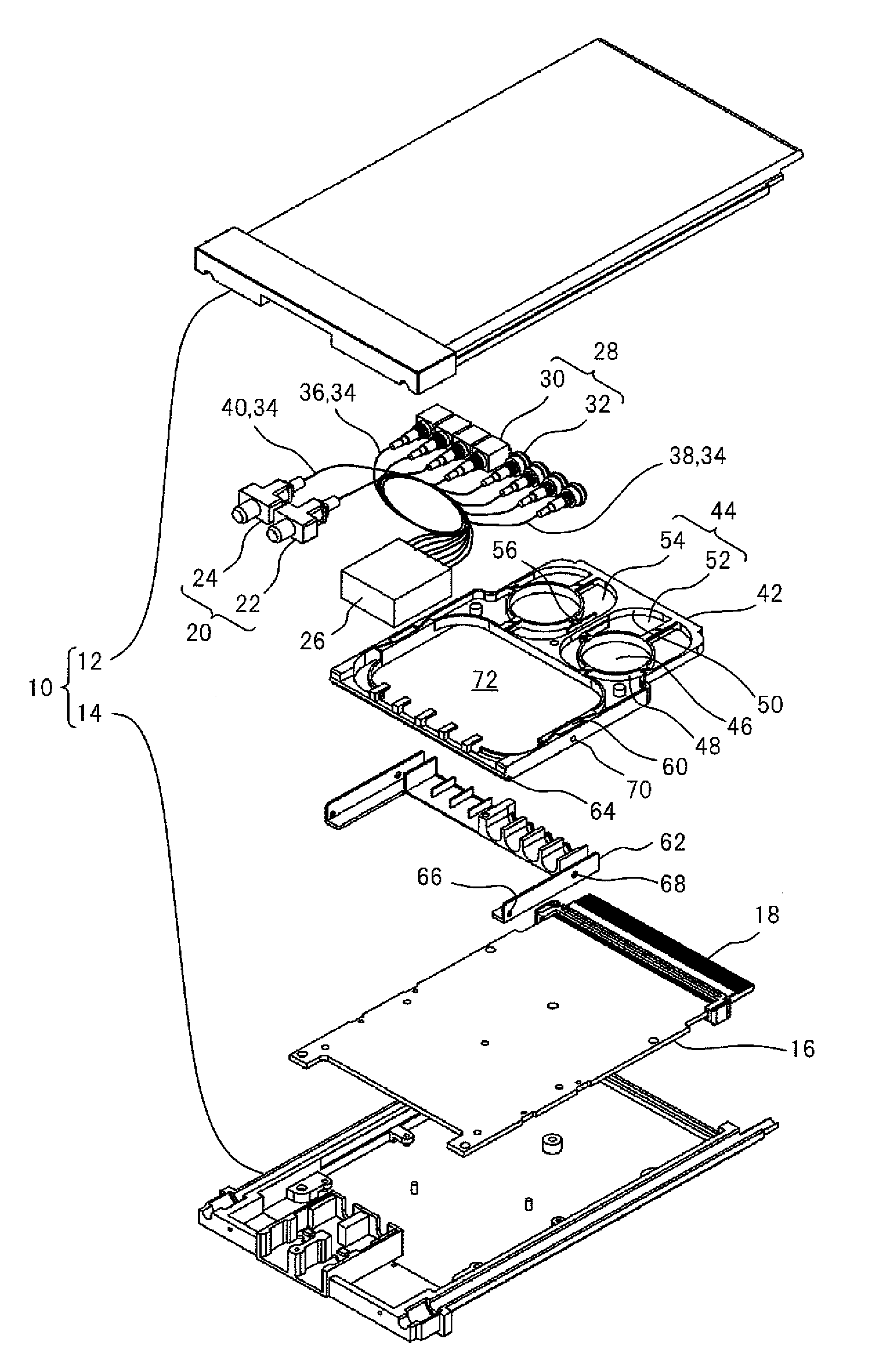
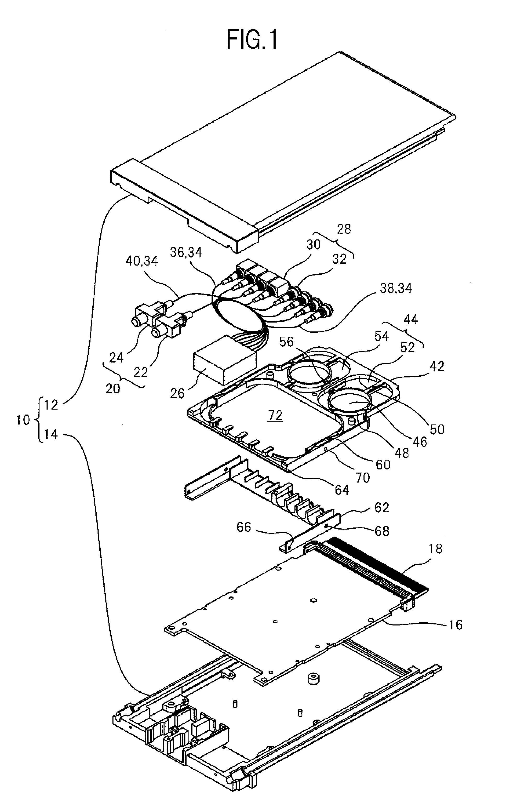
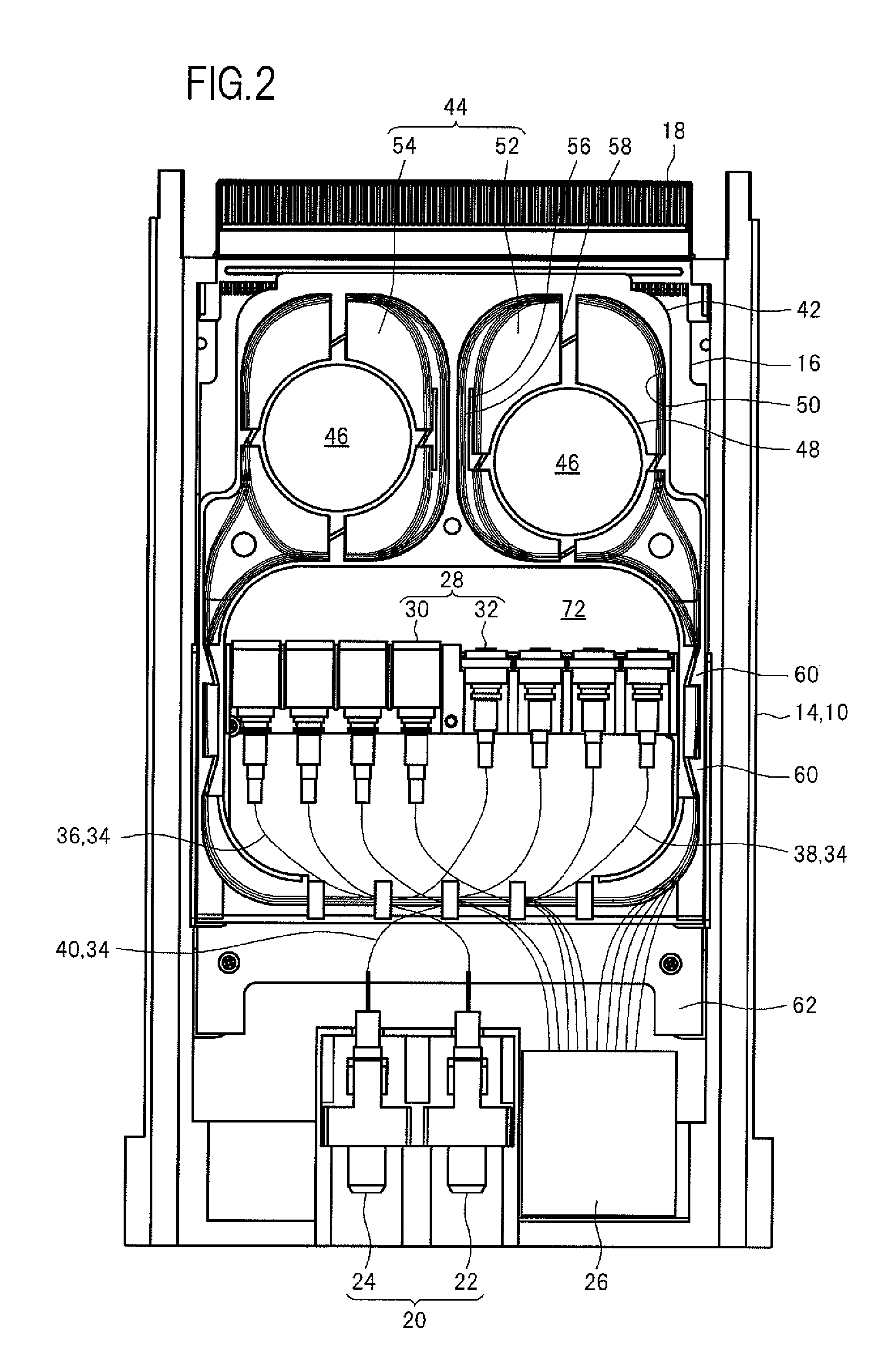
[0025]FIG. 1 is an exploded perspective view of an optical module according to a first embodiment to which the present invention is applied. FIG. 2 is a plan view illustrating an inner structure of the optical module.

[0026]The optical module includes a case 10. The case 10 is separated into an upper case 12 and a lower case 14, and the upper case 12 and the lower case 14 are fixed to each other with screws (not shown). The case 10 receives various components as follows.

[0027]The case 10 receives a circuit board 16. Specifically, the circuit board 16 is fixed to the lower case 14. The circuit board 16 includes a wiring pattern (not shown) formed thereon and electronic components (not shown) mounted thereon, and is provided with a terminal 18 for electrical connection to the outside of the circuit board 16.

[0028]The case 10 further receives a pair of connectors 20 for optical connection to the outside thereof. The connectors 20 are classified into an input connector 22 and an output c...

second embodiment

[0045]FIG. 5 is a plan view of an optical module according to a second embodiment to which the present invention is applied.

[0046]In the second embodiment, through a shaft 274, a tray 242 is rotatably fixed to a circuit board 216. The circuit board 216 is provided with a pin 276 disposed within a range of a track described by the rotating tray 242. The pin 276 serves as a stopper to restrict movement to one direction within a restricted range of the tray 242. Note that the restriction of movement to the other direction can be similarly performed.

[0047]Also in the second embodiment, the tray 242 is fixed with respect to a case (not shown) so as to be reciprocatingly movable only within the restricted range. The tray 242 is moved from a position to another position within the restricted range so as to be moved away from an electrical connection section 278 between optical assemblies (not shown) and the circuit board 216. Other structures, actions, and effects of the second embodiment ...

third embodiment

[0048]FIG. 6A and FIG. 6B are a plan view and a side view, respectively, of an optical module according to a third embodiment to which the present invention is applied.

[0049]In the third embodiment, guide rails 380 are fixed to a circuit board 316. A tray 342 is reciprocatingly movable while being guided with the guide rails 380. In other words, the tray 342 is slidably fixed with respect to a case (not shown).

[0050]The guide rails 380 are provided with slits 382 in a longitudinal direction thereof. Protrusions 384 formed in the tray 342 are moved in the slits 382 along with sliding of the tray 342, respectively. The Protrusions 384 function as stoppers.

[0051]Also in the third embodiment, the tray 342 is fixed with respect to a case (not shown) so as to be reciprocatingly movable only within the restricted range. The tray 342 is moved from a position to another position within the restricted range so as to be moved away from an electrical connection section 386 between optical assem...


PUM


Abstract

Provided is an optical module including: an optical assembly incorporating a light emitting or receiving device for converting one of an electrical signal and an optical signal into another of the electrical signal and the optical signal; a circuit board electrically connected to the optical assembly; an optical fiber optically connected to the optical assembly; a tray for winding the optical fiber therein and pulling out the optical fiber therefrom; and a case receiving the optical assembly, the circuit board, the optical fiber, and the tray. In the optical module, the tray is fixed with respect to the case so as to be reciprocatingly movable only within a restricted range, and the tray is moved from a position to another position within the restricted range so as to be moved away from an electrical connection section between the optical assembly and the circuit board.

Description

CROSS-REFERENCE TO RELATED APPLICATION[0001]The present application claims priority from Japanese application JP2009-176664 filed on Jul. 29, 2009, the content of which is hereby incorporated by reference into this application.BACKGROUND OF THE INVENTION[0002]1. Field of the Invention[0003]The present invention relates to an optical module.[0004]2. Description of the Related Art[0005]There has been known an optical module including: an optical assembly incorporating a light emitting device or a light receiving device for converting an electrical signal into an optical signal and vice versa; an optical fiber optically connected to the optical assembly; a circuit board to which the optical assembly is electrically connected; and a terminal formed in the circuit board. Further, there has been known that the optical fiber is wound in a tray, to thereby accommodate extra length (see Japanese Patent Application Laid-open No. 2003-107249 and Japanese Patent Application Laid-open No. 2003-3...

Claims


Application Information

Patent Timeline
Patent Type & Authority Applications(United States)
IPC IPC(8): G02B6/00
CPCG02B6/4453
Inventor OMORI, KOICHIISHII, HIROYOSHIOTAKE, TOSHIKAZU
Owner LUMENTUM JAPAN INC
Why Eureka
Try Eureka