Polymer-Metallic Reagent Head

Inactive Publication Date: 2011-02-03
PULSAFEEDER
View PDF1 Cites 0 Cited by
  • Summary
  • Abstract
  • Description
  • Claims
  • Application Information

AI Technical Summary

Benefits of technology

[0010]The present disclosure meets the above described need by providing a metering-pump reagent head which utilizes polymer-co

Problems solved by technology

Often these process fluids are corrosive liquids, such as, for example, sulphuric acid or sodium hypochlorite, that may not be compatible with traditional reagent head materials (e.g. iron or steel).
These exotic alloys, however, are expensive and may drive the cost of a reagent head to over $5,000.
However, other properties (e.g. strength, ductility, and the like) make PTFE a poor choice as the primary material in a reagent head.
However, the properties that make PTFE useful (e.g. low reactivity) also make the bond between PTFE and the coated metal less than ideal in a metering pump reagent head.
During the vacuum phase of the pressure-vacuum cycle used to move liquid through the head, the PTFE-metal bond is subject to enormous stresses and may suffer a mechanical failure.

Method used


Image

  • Polymer-Metallic Reagent Head
  • Polymer-Metallic Reagent Head
  • Polymer-Metallic Reagent Head

Examples


Embodiment Construction

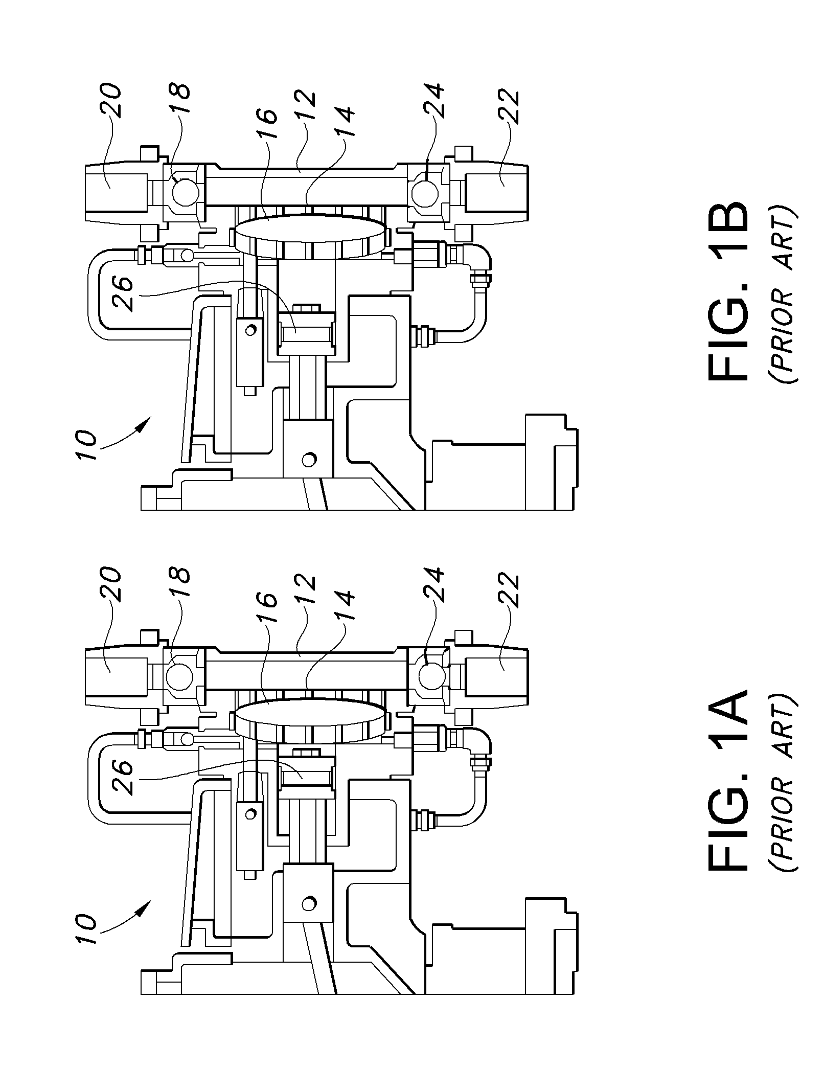
[0033]FIGS. 1a and 1b depict a metering pump 10 having a reagent head 12. In such reagent heads 12, a process fluid is pulled through an inlet 22 into a pumping chamber 14 by the vacuum created by a diaphragm 16 moving rearward (away from the pumping chamber 14) and expanding the volume of the pumping chamber 14. An inlet check valve 24 located at the inlet 22 may open by the vacuum created by the diaphragm 16 to allow process fluid to flow from the inlet 22. An outlet check valve 18 may be located at an outlet 20 of the pumping chamber 14 in order to prevent process fluid from re-entering the pumping chamber 14 from the outlet side. FIG. 1b depicts where the diaphragm 16 is in a rearward position, the inlet check valve 24 is open, and the outlet check valve 18 is closed.

[0034]Similarly, when the diaphragm 16 is moved forward (toward the pumping chamber 14) by the piston 26, the volume of process fluid which may be contained in the pumping chamber 14 is reduced, thereby forcing proc...


PUM


Abstract

A reagent head has a housing, an inlet and an outlet. Check valves and other details are not shown for clarity. The reagent head may have a dish where a diaphragm may seat when in a fully forward position. The reagent head may be constructed primarily from a high-strength material, e.g. ductile iron, in a substrate layer. The reagent head may also comprise a polymer layer. The polymer-metal interface may incorporate key grooves to provide an increased surface area for the polymer-metal bond. The key grooves may be any shape which increases the bonding surface area. Certain key groove cross-sectional shapes, such as dovetails, will create an interlocking interface that may provide increase resistance to separation of the polymer layer from the substrate layer.

Description

CROSS-REFERENCE TO RELATED APPLICATION[0001]This application claims the benefit of priority to U.S. provisional patent application Ser. No. 61 / 176,939, filed on May 10, 2009, now pending, the disclosure of which is incorporated herein by reference.FIELD OF THE INVENTION[0002]The present invention relates to pumps, and more specifically, to reagent heads used with pumps.BACKGROUND OF THE INVENTION[0003]Metering pumps are used to pump liquids in precise amounts and / or flow rates. These pumps may operate by using a piston which operates in a hydraulic reservoir. A diaphragm may separate the hydraulic reservoir from the liquid being pumped (“process fluid”). In such a pump, forward movement of the piston transmits hydraulic force against the diaphragm. The diaphragm moves in relation to the piston and forces process fluid through an outlet check valve. Conversely, rearward movement of the piston causes the diaphragm to suction process fluid from an input check valve into the pump head (...

Claims


Application Information

Patent Timeline
IPC IPC(8): F04B43/067
CPCF04B13/00F05C2225/00F04B53/16
Inventor MUSCARELLA, STEPHEN B.YANUS, JAMES R.
Owner PULSAFEEDER
Why Eureka
Try Eureka