

Temperature-controlled battery device and method for it
a battery device and temperature control technology, applied in the field of battery devices, can solve the problems of almost totally unimportant temperature range in the provided field of application, in which the battery is to be installed, and achieve the effect of wide energy rang
- Summary
- Abstract
- Description
- Claims
- Application Information
AI Technical Summary
Benefits of technology
Problems solved by technology
Method used
Image

Examples
Embodiment Construction
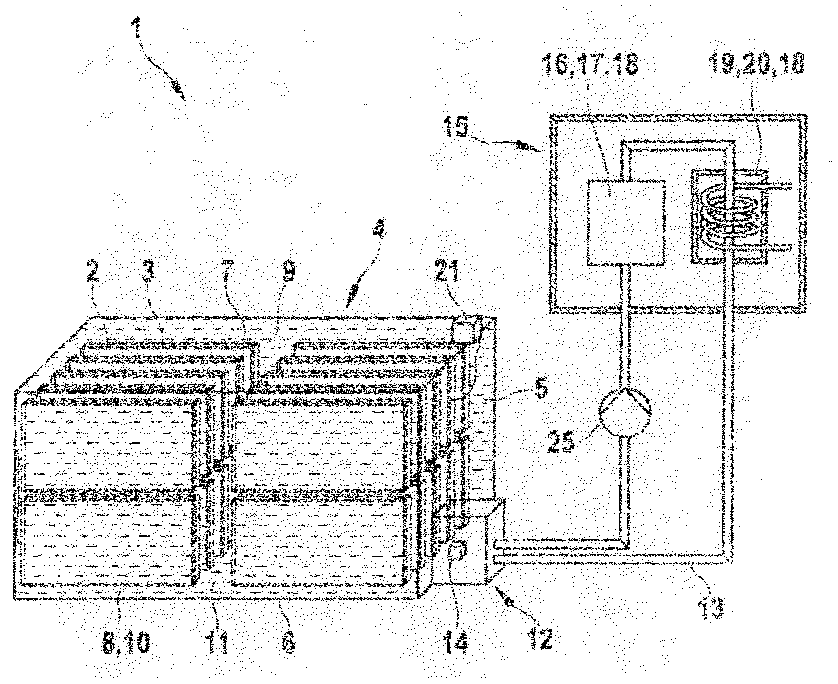
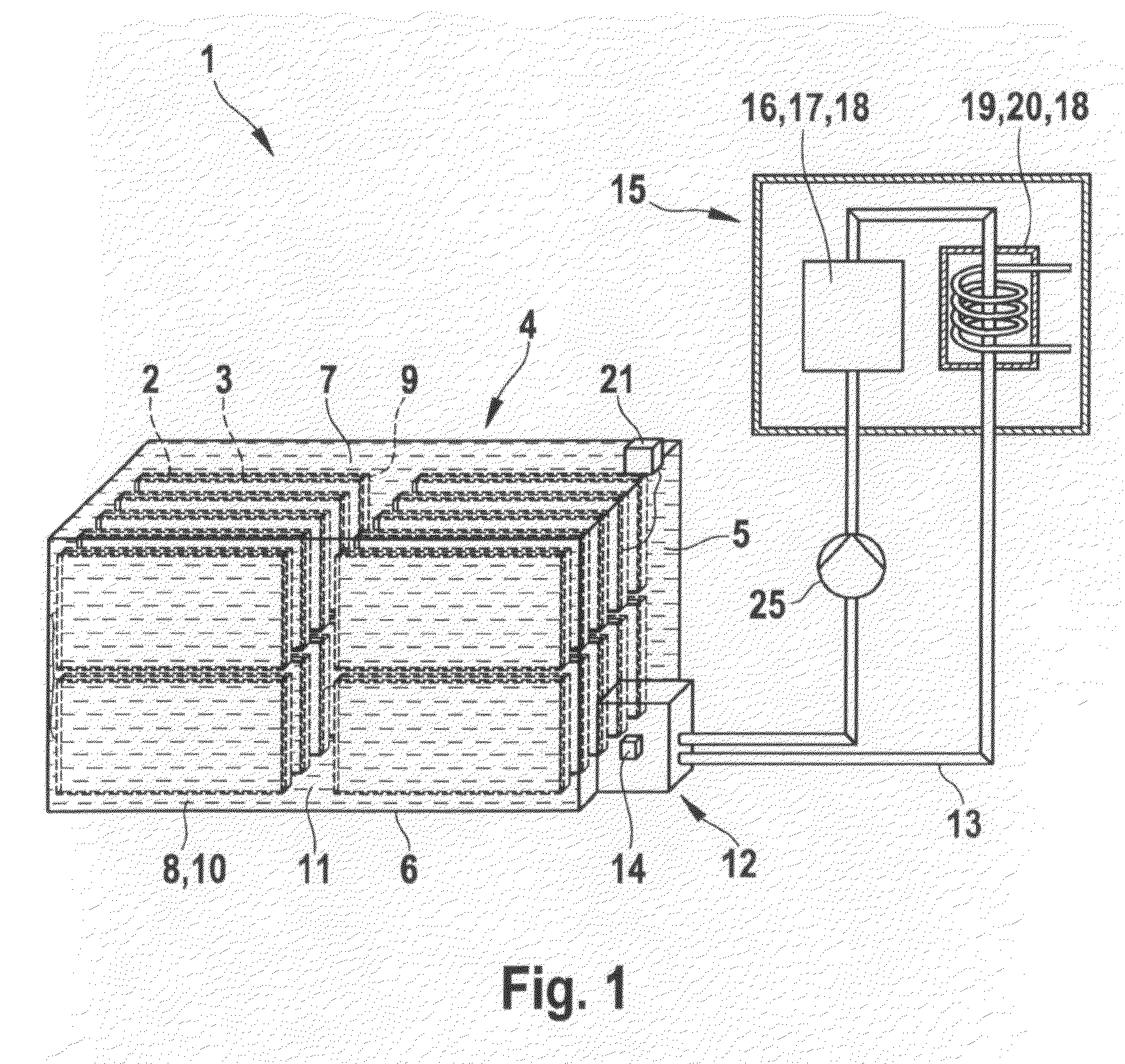
[0020]FIG. 1 shows a schematic representation of a battery device 1, made up of several batteries 2, that are developed as planar individual cells 3. These have been inserted, at a distance from one another, in a housing 4, the individual batteries 2 in each case being at a distance from sidewalls 5 and a bottom 6 and a cover 7 of housing 4. Housing 4 is filled completely with a heating and / or cooling medium 8. Batteries 2 are insulated and protected from heating and / or cooling medium 8 by an enclosure 9, that in each case individually envelops each planar individual cell 3. In this case, heating and / or cooling medium 8 is an incombustible medium 10, which contains a fireproofing agent 11 as well. Housing 4 has an interface adequate quantity that battery device 1 reaches the required temperature level. Battery device 1 also has a terminal block 21 for the electrical contacting of battery device 1 to devices lying outside of itself, especially for contacting to electrical consumers o...
PUM
| Property | Measurement | Unit |
|---|---|---|
| temperature | aaaaa | aaaaa |
| temperature | aaaaa | aaaaa |
| temperature | aaaaa | aaaaa |
Abstract
Description
Claims
Application Information