Anode, battery, and methods of manufacturing them

a battery and anode technology, applied in the field of anodes, can solve the problems of easy lowering of discharge capacity and difficult to obtain sufficient cycle characteristics, and achieve the effects of improving the cycle characteristics of secondary batteries, high performance, and easy decomposition of electrolytic solutions

Inactive Publication Date: 2011-02-03
SONY CORP
View PDF1 Cites 5 Cited by
  • Summary
  • Abstract
  • Description
  • Claims
  • Application Information

AI Technical Summary

Benefits of technology

[0013]According to the anode and the method of manufacturing it, or the battery and the method of manufacturing it of the embodiments of the invention, the anode active material layer of the anode contains the anode material that is capable of inserting and extracting electrode reactant and has at least one of a metal element and a metalloid element. In this case, in the case where the coat containing the metal salt having sulfur and oxygen is formed on the anode active material layer before charge and discharge, the chemical stability of the anode is improved, and thus decomposition reaction of the electrolytic solution is inhibited. Otherwise, in the case where the compound having a sulfonyl group is contained in the electrolytic solution, once charge and discharge are performed, the coat containing the metal salt having sulfur and oxygen is formed on the anode active material layer. In this case, at least one peak of ions selected from the group consisting of positive secondary ions (Li3SO4+, Li3SO3+, Li2SO3+, and Li2SO2+) and negative secondary ions (LiSO4−, LiSO3−, SO3−, and SO2−) is obtained by surface analysis of the anode using Time of Flight Secondary Ion Mass Spectrometry after charge and discharge, and thus decomposition reaction of the electrolytic solution is inhibited. Therefore, the cycle characteristics may be improved. In this case, since the coat is formed by using the solution containing a metal salt having sulfur and oxygen, a favorable coat may be easily formed compared to a case using a method necessitating particular environmental conditions such as reduced pressure environment.

Problems solved by technology

However, in the lithium ion secondary battery using silicon or the like as an anode active material, there has been the following issue.
In the result, when charge and discharge are repeated, the discharge capacity is easily lowered and thus it is hard to obtain sufficient cycle characteristics.

Method used


Image

  • Anode, battery, and methods of manufacturing them
  • Anode, battery, and methods of manufacturing them
  • Anode, battery, and methods of manufacturing them

Examples


first embodiment

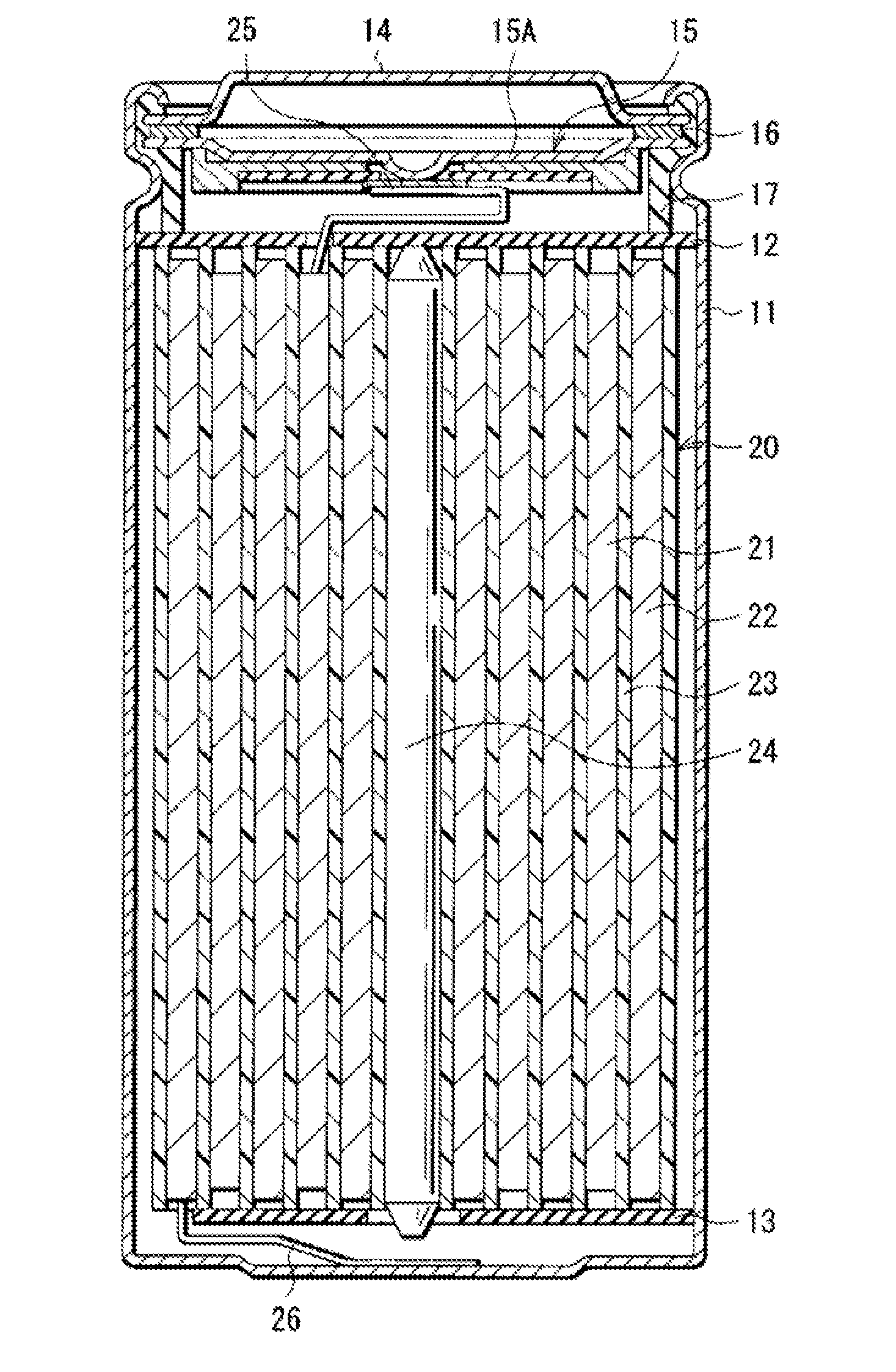
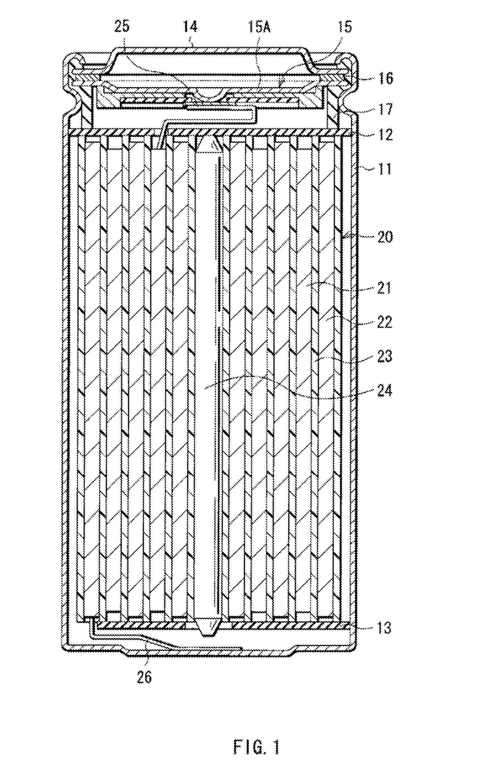
[0030]FIG. 1 shows a cross sectional structure of a battery according to a first embodiment of the invention. The battery is, for example, a lithium ion secondary battery in which the anode capacity is expressed based on insertion and extraction of lithium as an electrode reactant. The anode of the invention is applied to the secondary battery described below.

[0031]In the secondary battery, a spirally wound electrode body 20 in which a cathode 21 and an anode 22 are layered with a separator 23 in between and spirally wound, and a pair of insulating plates 12 and 13 are contained in a battery can 11 in the shape of an approximately hollow cylinder. The battery can 11 is made of, for example, iron plated by nickel. One end of the battery can 11 is closed, and the other end thereof is opened. The pair of insulating plates 12 and 13 is respectively arranged perpendicular to the winding periphery face, so that the spirally wound electrode body 20 is sandwiched between the insulating plat...

second embodiment

[0090]FIG. 4 shows an exploded perspective structure of a battery according to a second embodiment of the invention. In the battery, mainly, a spirally wound electrode body 30 to which a cathode lead 31 and an anode lead 32 are attached is contained in a film package member 40. The battery is a lithium ion secondary battery as in the first embodiment. The battery structure using the film package member 40 is called laminated film type.

[0091]The cathode lead 31 and the anode lead 32 are respectively derived in the same direction from inside to outside of the package member 40. The cathode lead 31 is made of, for example, a metal material such as aluminum, and the anode lead 32 is made of, for example, a metal material such as copper, nickel, and stainless. The metal material composing the cathode lead 31 and the anode lead 32 is in the shape of, for example, a thin plate or mesh.

[0092]The package member 40 is made of a rectangular aluminum laminated film in which, for example, a nylo...

third embodiment

[0107]FIG. 7 shows a cross sectional structure of a battery according to a third embodiment of the invention. In the secondary battery, a cathode 51 is contained in a package can 54 and an anode 52 is bonded to a package cup 55, the resultant is layered with a separator 53 impregnated with an electrolytic solution in between, and the resultant laminated body is caulked with a gasket 56. The secondary battery is, for example, a lithium ion secondary battery as in the foregoing first embodiment. The battery structure using the package can 54 and the package cup 55 is called coin type.

[0108]The structures of the package can 54, the package cup 55, and the gasket 56 are respectively similar to the structures of the battery can 11 and the gasket 17 in the foregoing first embodiment.

[0109]The cathode 51 has, for example, a structure in which a cathode active material layer 51B is provided on a single face of a cathode current collector 61A. The anode 52 has, for example, a structure in wh...


PUM

PropertyMeasurementUnit
ion conductivityaaaaaaaaaa
chargesaaaaaaaaaa
thicknessaaaaaaaaaa

Abstract

A battery including an electrolytic solution. The electrolytic solution including a compound having a sulfonyl group and at least one peak of ions is selected from the group consisting of Li3SO4+, Li3SO3+, Li2SO3+, and Li2SO2+ as a positive secondary ion and LiSO4−, LiSO3−, SO3−, and SO2− as a negative secondary ion is obtained by surface analysis of the anode using Time of Flight Secondary Ion Mass Spectrometry after charge and discharge.

Description

CROSS-REFERENCE TO RELATED APPLICATIONS[0001]This application is a division of U.S. application Ser. No. 12 / 144,766, entitled “ANODE, BATTERY, AND METHODS OF MANUFACTURING THEM,” filed on Jun. 24, 2008, the entirety of which is incorporated herein by reference to the extent permitted by law. The present invention claims priority to Japanese Patent Application No. 2007-190977, filed Jul. 23, 2007, the entirety of which is also incorporated herein by reference to the extent permitted by law.BACKGROUND OF INVENTION[0002]The present invention relates to an anode having an anode active material layer on an anode current collector, a battery using it, and methods of manufacturing them.[0003]In recent years, portable electronic devices such as combination cameras (videotape recorder), digital still cameras, mobile phones, Personal Digital Assistants, and notebook personal computers have been widely used, and it is strongly demanded to reduce their size and weight and to achieve their long ...

Claims


Application Information

Patent Timeline
Patent Type & Authority Applications(United States)
IPC IPC(8): H01M10/26H01M4/134H01M4/136H01M4/1395H01M4/1397H01M4/58H01M10/052H01M10/0567H01M10/058
CPCH01M4/0404H01M4/134H01M4/38Y10T29/49108H01M10/0567Y02E60/122H01M10/0525H01M4/386H01M4/387Y02E60/10Y02P70/50H01M4/02
Inventor NAKAI, HIDEKIIHARA, MASAYUKIYAMAGUCHI, HIROYUKI
Owner SONY CORP
Why Eureka
Try Eureka