Prosthesis Coupling Device and Method

a technology of prosthesis and coupling device, which is applied in the direction of prosthesis, blood vessels, manufacturing tools, etc., can solve the problems of consequential limitations on the design of modules and particular problems that can aris

Active Publication Date: 2011-02-03
COOK MEDICAL TECH LLC
View PDF9 Cites 11 Cited by
  • Summary
  • Abstract
  • Description
  • Claims
  • Application Information

AI Technical Summary

Benefits of technology

In practice, the space between the inner and outer coupling elements will be filled with vascular fluid, aiding in the sealing on the coupling and prosthesis to the vessel.

Problems solved by technology

This necessitates careful manufacturing and imposes consequential limitations on the design of the modules.
Particular problems can arise in the case of aneurisms, for example, where the vessel is enlarged at the ends of the prosthesis or at the point of coupling of two modules of a modular prosthesis.

Method used


Image

  • Prosthesis Coupling Device and Method
  • Prosthesis Coupling Device and Method
  • Prosthesis Coupling Device and Method

Examples


Embodiment Construction

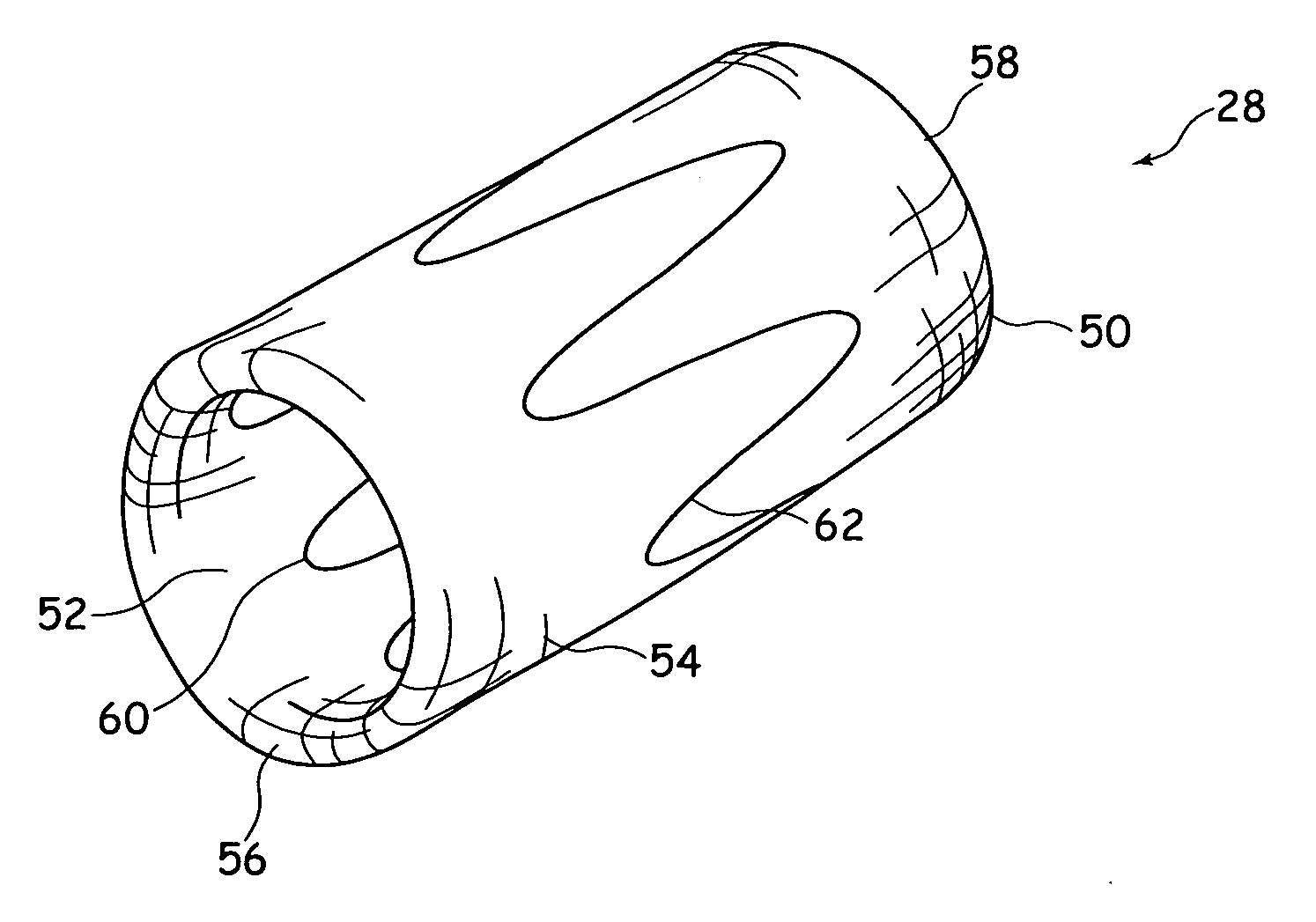
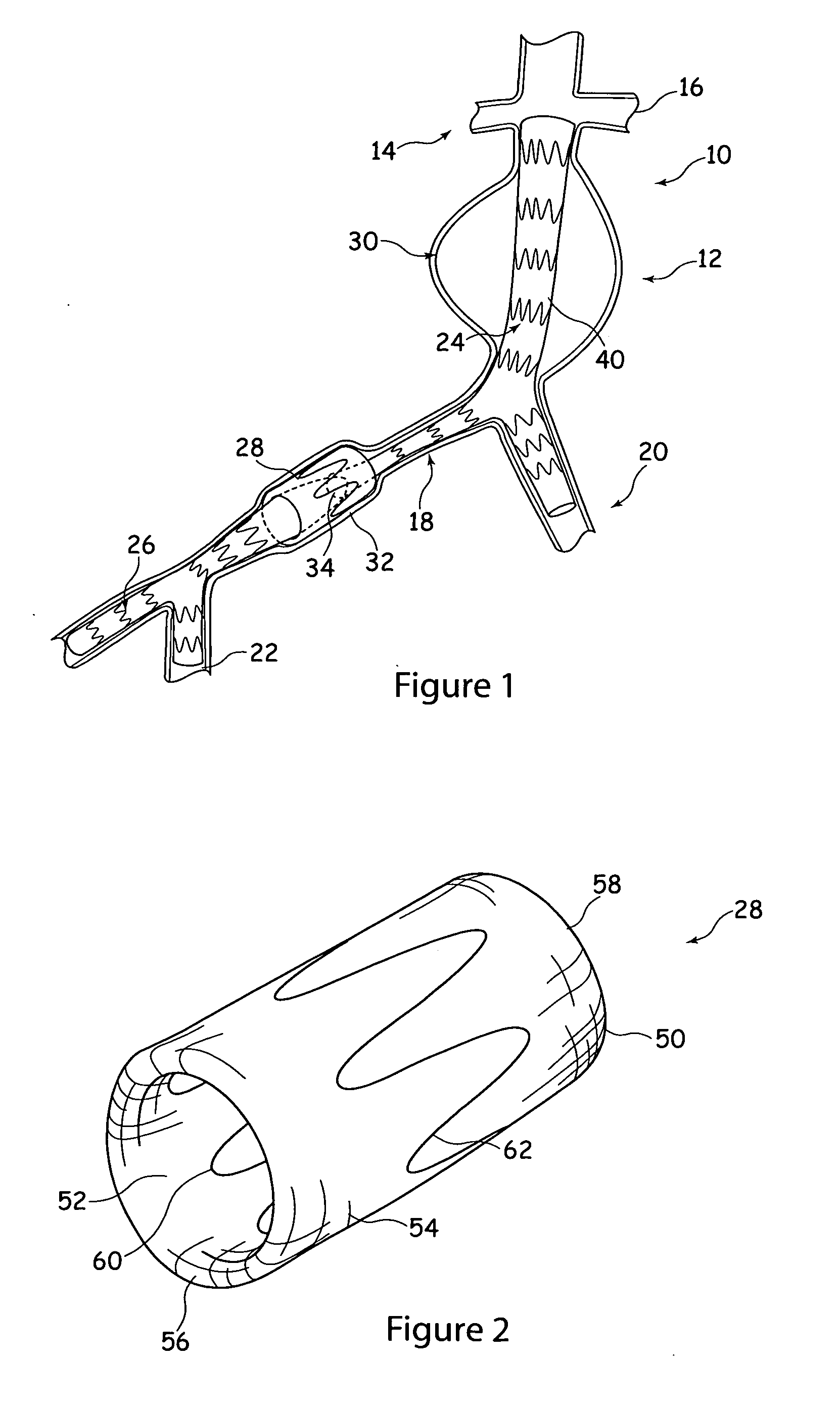
Referring to FIG. 1, there is shown a double branched stent-graft 10 located within the superior mesenteric artery 12, just below the renal arteries 14, 16, and branching into the common iliac arteries 18 and 20. The stent graft 10 branches a second time, into the femoral artery 22.

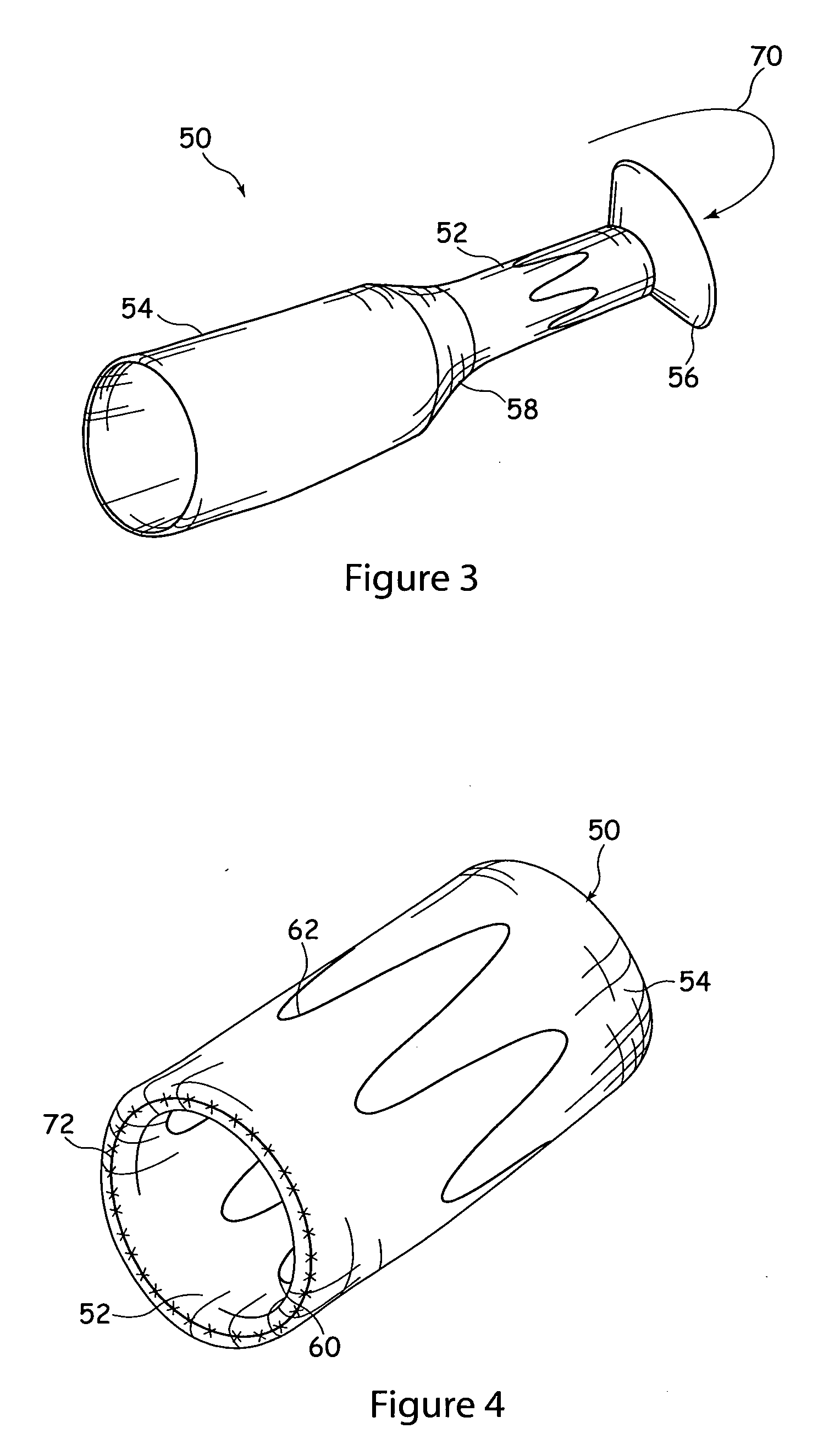
For this purpose, the stent graft 10 is formed as two modules 24, 26 which are coupled to one another by an embodiment of coupling device 28 of the type taught herein and described in further detail below.

In this instance, an aneurysm 30 is located in the superior mesenteric artery 12, which has been isolated by the upper body portion 40 of the stent-graft 10, as well as a smaller aneurysm 32 in the iliac artery 18, at the location of the connection 34 between the two stent-graft modules 24, 26.

A conventional modular stent-graft 10 would couple the two modules 24, 26 by overlapping these and causing the inner-most section to expand against the outer section. For this purpose, the stent-graft sections of t...


PUM

PropertyMeasurementUnit
inner diameteraaaaaaaaaa
diametersaaaaaaaaaa

Abstract

A coupling device (28) is formed of a double tubing (50) of a substantially non-porous membrane material, typically a conventional graft material, that is of inner and outer layers of membrane material (52, 54). The inner and outer layers (52, 54) are coupled by bridging rings (56, 58) which allow the layers (52, 54) to be spaced from one another in use. Attached to the inner and outer layers (52, 54) are first and second stents (60, 62). The stent (60) is located on the inside of the double tubing, while the stent (62) is located on the outside of the double tubing (50). The device (28) can expand in effect to ‘bulge’ and thus to fill the gaps to the vessel wall and to the stent-graft sections (24, 26). The device can provide reliable coupling of stent-grafts in vessels of varying diameter or in vessels inflicted with one or more aneurysms.

Description

TECHNICAL FIELDThe present invention relates to a prosthesis coupling device, to a prosthetic assembly and to a method of making a coupling device.BACKGROUND ARTProstheses for the repair of vascular defects, including for example vascular aneurysms, are well known in the art. A common prosthesis for treatment of such a medical condition is a stent graft. It is also known to provide such prostheses in modular form, for example when it is necessary for the prosthesis to straddle a plurality of vessels, such as the superior mesenteric artery and the iliac arteries. Similarly, a modular prosthesis may be provided in cases where the dimensions of the artery or other vessel to be treated would vary substantially from one end of the prosthesis to the other. Yet another example is where a medical condition necessitates the use of different types of prosthesis along the length of the site to be treated.It is common for such modular prostheses to be coupled together by nesting one section wit...

Claims


Application Information

Patent Timeline
Patent Type & Authority Applications(United States)
IPC IPC(8): A61F2/82B23P11/00A61F2/06
CPCA61F2/064A61F2/07A61F2002/067A61F2250/006Y10T29/49826A61F2/89A61F2002/075A61F2220/0075A61F2250/0063
Inventor CHRISTIANSEN, FRANK K.IVANCEV, KRASNODAR
Owner COOK MEDICAL TECH LLC
Why Eureka
Try Eureka