Stent valve and method of using same

a technology of stent valve and stent valve, which is applied in the field of stent valve, can solve the problems of relative difficulties in properly expanding and implanting the stent valve, the performance of the stent valve is difficult to achieve, and the stent valve is difficult to implement. achieve the effect of improving the valve performan

Inactive Publication Date: 2011-02-03
GILAD RAN +2
View PDF3 Cites 186 Cited by
  • Summary
  • Abstract
  • Description
  • Claims
  • Application Information

AI Technical Summary

Benefits of technology

[0010]Advantageously, the stent valve is positionable in vessels having irregular geometries. For example, the stent valve is relatively easily positioned substantially adjacent a stenotic region of a blood vessel such that the valve is positioned in a region of the blood vessel that is substantially larger than the stenotic region.
[0011]Therefore, the valve and the valve supporting section is relatively easy to extend to a relatively large diameter in the body vessel, which has a potential to improve the performance of the valve as compared to valves that are expandable only to relatively small diameters.
[0012]In some embodiments of the invention, the stent valve includes an auxiliary anchoring section allowing anchoring the stent valve at another location in the body vessel. The auxiliary anchoring section helps in reducing the risk that the stent valve will move with respect to the body vessel after it has been moved to the scaffold expanded configuration.

Problems solved by technology

Currently available stent valves are difficult to implement in many locations.
For example, stent valves implanted in proximity to a stenotic region of a vessel suffer from relatively poor performance as the valve is then typically expanded to a relatively small diameter.
Such bifurcations typically have irregular geometries that result in relative difficulties in properly expanding and implanting the stent valve.
While some existing stents that do not include valves may be positioned at similar locations, these stents typically do not take into account constraints caused by the presence of a valve.
They are therefore often not readily usable to manufacture stent valves that solve at least some of the above-mentioned problems.

Method used


Image

  • Stent valve and method of using same
  • Stent valve and method of using same
  • Stent valve and method of using same

Examples


Embodiment Construction

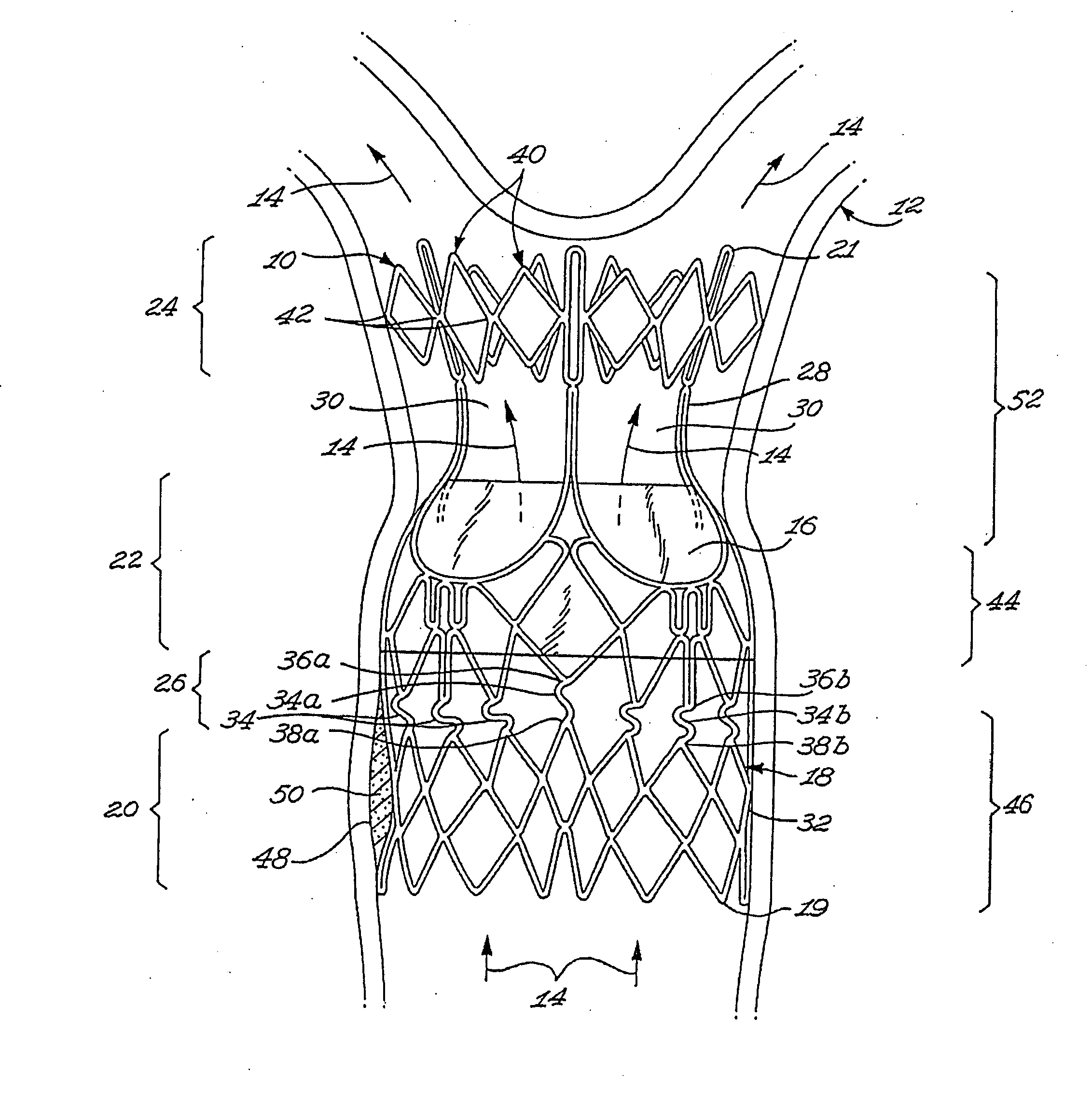
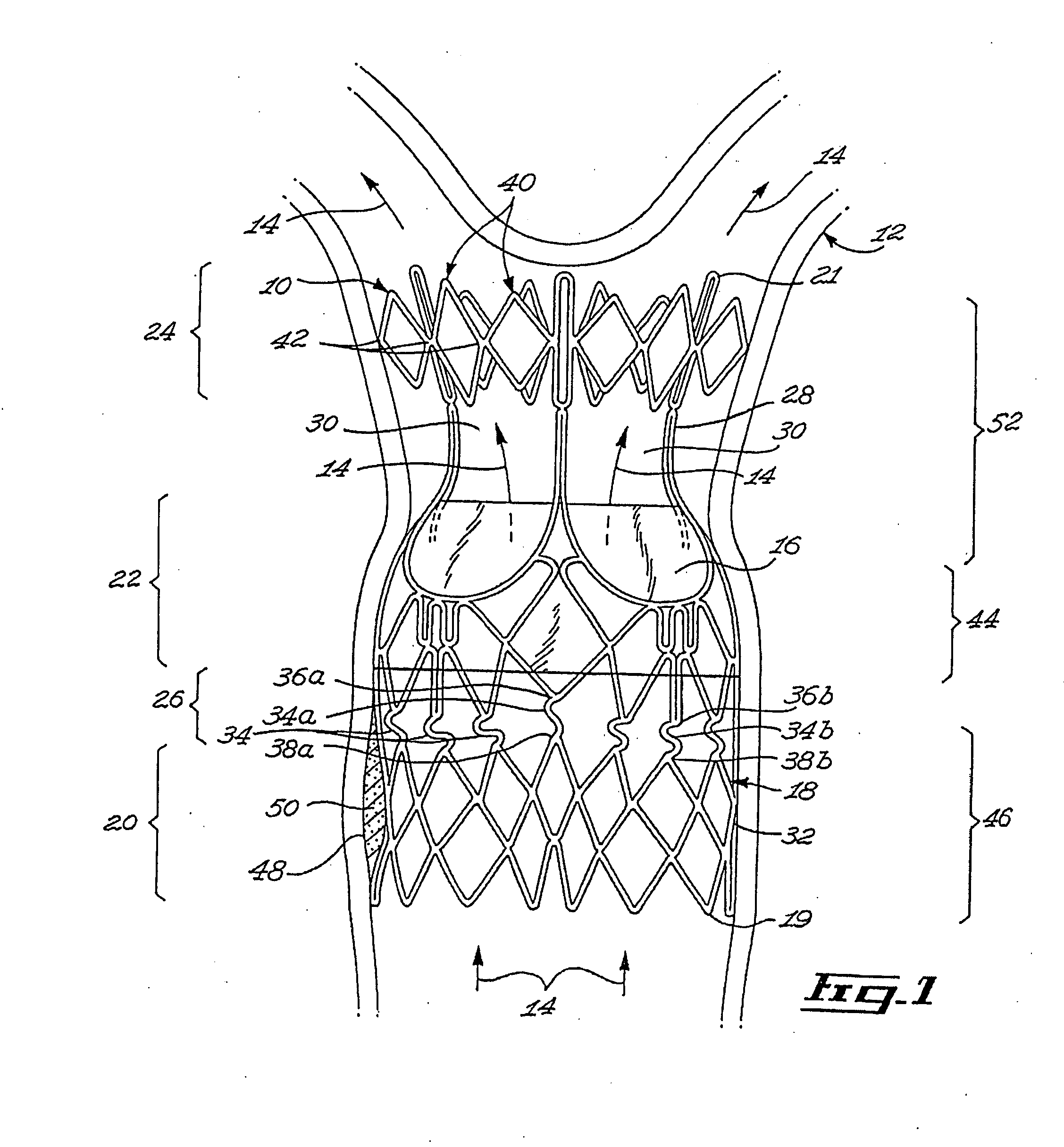
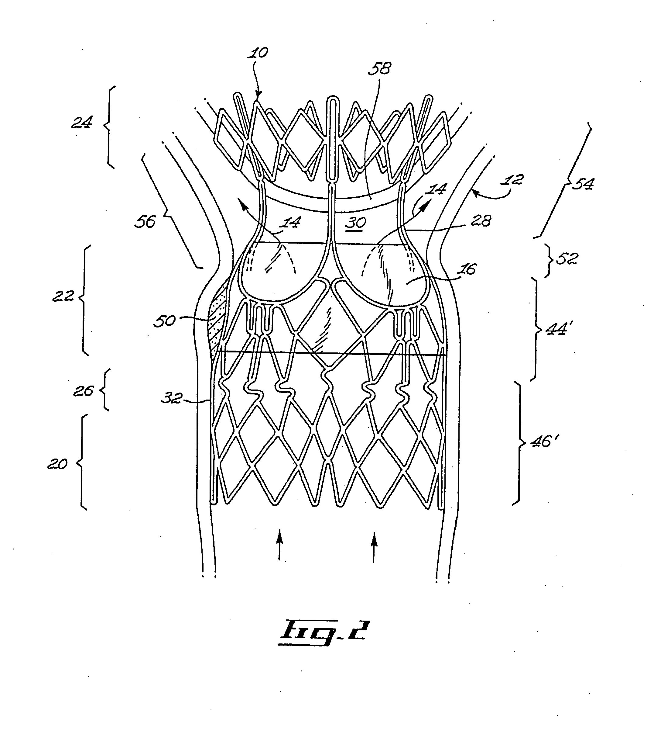
[0031]FIGS. 1 and 3 illustrate a stent valve 10 in accordance with an embodiment of the present invention. The stent valve 10 is insertable in a body vessel 12 containing a body fluid. The movement of the body fluid through the body vessel and through the stent valve 10 is represented by the arrows 14.

[0032]The stent valve 10 includes a valve 16 for at least partially controlling the flow of the body fluid in the body vessel 12. The stent valve 10 further includes a scaffold 18. The scaffold 18 is substantially radially expandable from a scaffold retracted configuration (for example, as shown in FIG. 6) to a scaffold expanded configuration, shown for example in FIG. 1. For example, the scaffold 18 includes interlinked struts 32 that are movable substantially radially so as to allow the scaffold to be moved between the scaffold retracted and expanded configurations.

[0033]Referring to FIG. 1, the scaffold 18 defines a scaffold first longitudinal end 19 and an opposed scaffold second l...


PUM


Abstract

A stent valve insertable in a body vessel containing a body fluid. The stent valve includes: a valve for at least partially controlling the flow of the body fluid in the body vessel; and a scaffold, the scaffold including: an anchoring section for anchoring the scaffold to said body vessel and a valve supporting section supporting the valve. The scaffold is substantially radially expandable from a scaffold retracted configuration to a scaffold expanded configuration. The valve supporting section is expandable over a greater range of radial expansion than the anchoring section.

Description

[0001]The present application is a Continuation of U.S. patent application Ser. No. 11 / 250,445 filed on Oct. 17, 2005, which application is a Continuation-in-Part of U.S. patent application Ser. No. 10 / 841,816 filed on May 10, 2004 and also claims priority from Provisional Application Ser. No. 60 / 619,298 filed on Oct. 15, 2004. The aforementioned applications are hereby incorporated by reference herein in their entirety.[0002]I hereby claim the benefit under Title 35, United States Code, §120, of the prior, co-pending United States application listed herinabove and, insofar as the subject matter of each of the claims of this application is not disclosed in the manner provided by the first paragraph of Title 35, United States Codes §112, I acknowledge the duty to disclose material information as defined in Title 37, Code of Federal Regulations, §1.56(a), which occurred between the filing date of this application and the national or PCT international filing date of this application Se...

Claims


Application Information

Patent Timeline
Patent Type & Authority Applications(United States)
IPC IPC(8): A61F2/82
CPCA61F2/2418A61F2230/0054A61F2250/0018A61F2002/825
Inventor GILAD, RANBAYLIS, FRANKBISDILLAH, YOUSSEF
Owner GILAD RAN
Why Eureka
Try Eureka