Engine Control Apparatus

a control apparatus and engine technology, applied in the direction of electrical control, process and machine control, instruments, etc., can solve the problems of deteriorating stability (operability) of the engine, lean air-fuel ratio of the cylinder, and variable torque between the cylinders, so as to achieve stable exhaust performance and fuel consumption performance, and stable operation of the engine

Active Publication Date: 2011-02-03
HITACHI AUTOMOTIVE SYST LTD
View PDF2 Cites 22 Cited by
  • Summary
  • Abstract
  • Description
  • Claims
  • Application Information

AI Technical Summary

Benefits of technology

[0006]In the mechanism which controls the amount of fuel and the amount of air independently of each other, the amount of fuel and the amount of air may vary from one cylinder to another. In this case, attempting to perform control so as to eliminate only the variation in the air-fuel ratio among cylinders may result in a variation in torque among cylinders and may rather deteriorate stability (operability) of the engine.
[0007]For example, when the amount of air of only a specific cylinder increases unintentionally, only the air-fuel ratio of the cylinder becomes lean. When the leanness is corrected by increasing only the fuel injection amount of the cylinder, torque of only the cylinder in question increases and stability deteriorates.
[0008]The present invention has been implemented in view of the above described problems and it is an object of the present invention to provide an engine control apparatus that appropriately performs correction according to causes of errors and corrects variations in both the air-fuel ratio and torque.

Problems solved by technology

In this case, attempting to perform control so as to eliminate only the variation in the air-fuel ratio among cylinders may result in a variation in torque among cylinders and may rather deteriorate stability (operability) of the engine.
For example, when the amount of air of only a specific cylinder increases unintentionally, only the air-fuel ratio of the cylinder becomes lean.
When the leanness is corrected by increasing only the fuel injection amount of the cylinder, torque of only the cylinder in question increases and stability deteriorates.

Method used


Image

  • Engine Control Apparatus
  • Engine Control Apparatus
  • Engine Control Apparatus

Examples


embodiment 1

b> to FIG. 22

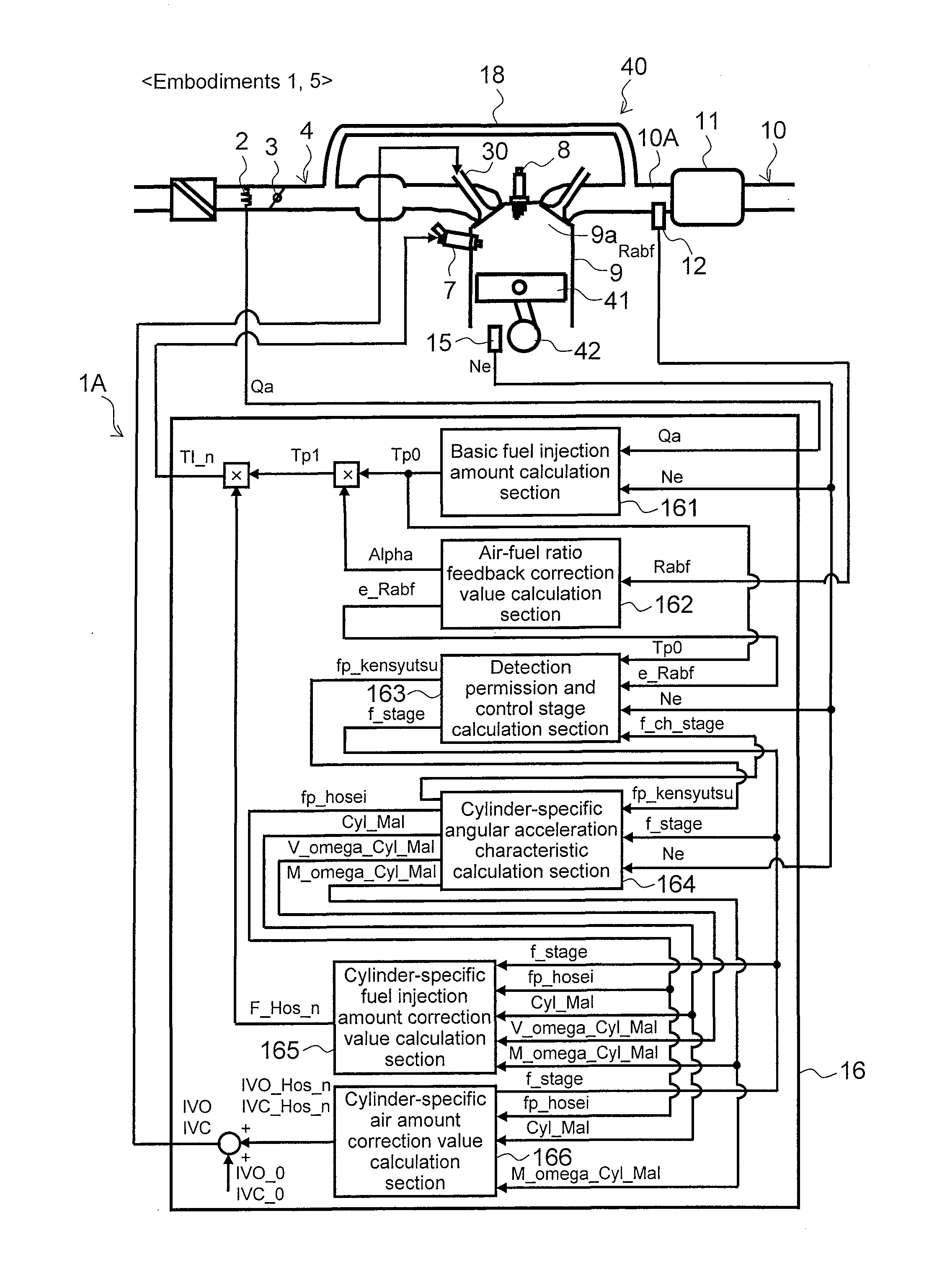
[0143]FIG. 16 is a control system diagram illustrating a control apparatus 1A according to Embodiments 1, 5. As shown in the function block diagram, the engine control unit 16 of the control apparatus 1A is provided with a basic fuel injection amount calculation section 161, an air-fuel ratio feedback correction value calculation section 162, a detection permission and control stage calculation section 163, a cylinder-specific angular acceleration characteristic calculation section 164, a cylinder-specific fuel injection amount correction value calculation section 165 and a cylinder-specific air amount correction value calculation section 166. These calculation sections are realized by the engine control unit 16 executing a control program.

[0144]The basic fuel injection amount calculation section 161 calculates a basic fuel injection amount Tp0 based on an amount of intake air Qa and an engine speed Ne. The air-fuel ratio feedback correction value calculation section 16...

embodiment 2

b> to FIG. 25

[0184]A case has been described in aforementioned Embodiment 1 where the amount of fuel of the abnormal cylinder is corrected so as to increase, the air-fuel ratio of the abnormal cylinder is corrected to the rich side, and when the torque of the abnormal cylinder after the correction is greater than the torque of the cylinders other than the abnormal cylinder, the amount of fuel and the amount of air of the abnormal cylinder are corrected so as to decrease, whereas in Embodiment 2, instead of correcting the amount of fuel and the amount of air of the abnormal cylinder so as to decrease, ignition timing of the abnormal cylinder is corrected so as to retard. That is, in Embodiment 2, the amount of fuel of the abnormal cylinder is corrected so as to increase, the air-fuel ratio of the abnormal cylinder is corrected to the rich side, and when the torque of the abnormal cylinder after the correction is greater than the torque of the cylinders other than the abnormal cylinde...

embodiment 3

b> to FIG. 29

[0200]Embodiment 3 corrects an amount of air of the abnormal cylinder so as to decrease and corrects the air-fuel ratio of the abnormal cylinder to the rich side, and corrects, when torque of the abnormal cylinder after the correction is smaller than torque of the cylinders other than the abnormal cylinder, the amount of fuel and the amount of air of the abnormal cylinder so as to increase.

[0201]FIG. 26 is a control system diagram illustrating a control apparatus 1C according to (Embodiments 3, 7).

[0202]Present Embodiment 3 is only different from above described Embodiment 1 in the specifications of the cylinder-specific angular acceleration characteristic calculation section 164, cylinder-specific fuel injection amount correction value calculation section 165 and cylinder-specific air amount correction value calculation section 166, and other means are substantially the same, and therefore only calculation sections having different specifications will be described with...


PUM


Abstract

The present invention performs correction appropriately according to errors in the fuel system and air system respectively and corrects both variations in the air-fuel ratio and torque. When the difference between a target air-fuel ratio and a real air-fuel ratio is equal to or below a predetermined value when feedback control based on the air-fuel ratio of an exhaust manifold 10A is in progress, the air-fuel ratio of a cylinder cyl_1 having the largest variation of angular acceleration is corrected to the rich side, for example, by increasing the amount of fuel. Angular acceleration per cylinder is then detected again and when the variation in angular acceleration among cylinders is not eliminated, it is judged that there is an error in the amount of air control of the cylinder having the largest variation and the amount of air, amount of fuel, ignition timing or the like are corrected.

Description

BACKGROUND OF THE INVENTION[0001]1. Field of the Invention[0002]The present invention relates to an engine control apparatus, and more particularly, to a control apparatus that detects and / or corrects variations in both the amount of fuel and the amount of air among cylinders.[0003]2. Background Art[0004]Against a background of problems with the global environment, there is an ever increasing demand for automobiles emitting less exhaust and less CO2 (less fuel consumption). In order to improve performance of engines, engines provided with a mechanism that controls the amount of fuel and amount of air supplied to the engine independently of each other, for example, by adopting a variable valve, are becoming widespread. In such engines, it is necessary to guarantee the performance of controlling the amount of fuel and the amount of air independently of each other in a practical environment, too.[0005]JP Patent Publication (Kokai) No. 2004-346807A discloses an invention that detects, w...

Claims


Application Information

Patent Timeline
Patent Type & Authority Applications(United States)
IPC IPC(8): F02D41/00
CPCF02D37/02F02D41/0085F02D2200/1012F02D41/1497F02D41/1454
Inventor NAKAGAWA, SHINJIKANETOSHI, KAZUHIKOKATOGI, KOUZOUICHIHARA, TAKANOBUOHSUGA, MINORU
Owner HITACHI AUTOMOTIVE SYST LTD
Why Eureka
Try Eureka