Real-time completion monitoring with acoustic waves

a technology of acoustic waves and completion monitoring, applied in the field of subterranean well monitoring, can solve the problems of large portion of the overall well cost, difficult deciphering, expensive and in real time, and achieve the effect of improving understanding

Active Publication Date: 2011-02-10
SHELL USA INC
View PDF16 Cites 44 Cited by
  • Summary
  • Abstract
  • Description
  • Claims
  • Application Information

AI Technical Summary

Benefits of technology

[0012]The present acoustic monitoring method can serve as a permanently installed monitor of the quality of the sandface. The acoustic monitoring methods constantly conduct both active checks of the sandscreen and its environment and passive monitoring of the reservoir. Early detection and proper diagnostics follow as a natural outcome of permanent monitoring, so that proper treatment (work-over) can be delivered before issues get out of hand. Permanent monitoring can also serve as an additional insurance to safeguard expensive completion and sand control devices, as well as the borehole itself. In addition, methods such as described herein can deliver streams of new data to that can enhance understanding of other sand-screen and completion issues and eventually contribute to proper resolution of many “well underperformance” problems.

Problems solved by technology

Completions lie at the heart of deepwater production and constitute a large portion of the overall well cost.
Sand screen plugging, incomplete packing, development of “hot spots” in screens, destabilization of the annular pack, fines migration, near-wellbore damage, cross-flow, differential depletion, compartmentalization, compaction represent a typical list of challenges that are extremely difficult to decipher based on just several permanent pressure and temperature gauges.
Many problems can be identified by production logging, but it is costly and not in real time.
However these new pressure and temperature data are unlikely to lead to unambiguous identification of the problems above because of multitude of parameters characterizing complex completions and reservoirs that remain unconstrained by our data.
For example, there is an issue of underperforming hydrocarbon production wells in the Gulf of Mexico.
Yet those boundaries are rarely confirmed by 4D seismic or other data.
Shale draping is an alternative reservoir-scale scenario that can lead to well underperformance.
In the context of deepwater completions there is an additional emphasis on sand control because it is believed that managing produced sand is generally a costly and mostly unworkable solution for the Gulf of Mexico, although it may work well in other places where there is some grain-to-grain cementation present.
The presence of sand control media between the reservoir and the wellbore introduces additional cost, complexity and requires proper management.
The high cost of deepwater well devices (sand screens etc) and intervention can justify the presence of smart surveillance tools that would not be economical in other environments.

Method used


Image

  • Real-time completion monitoring with acoustic waves
  • Real-time completion monitoring with acoustic waves
  • Real-time completion monitoring with acoustic waves

Examples


Embodiment Construction

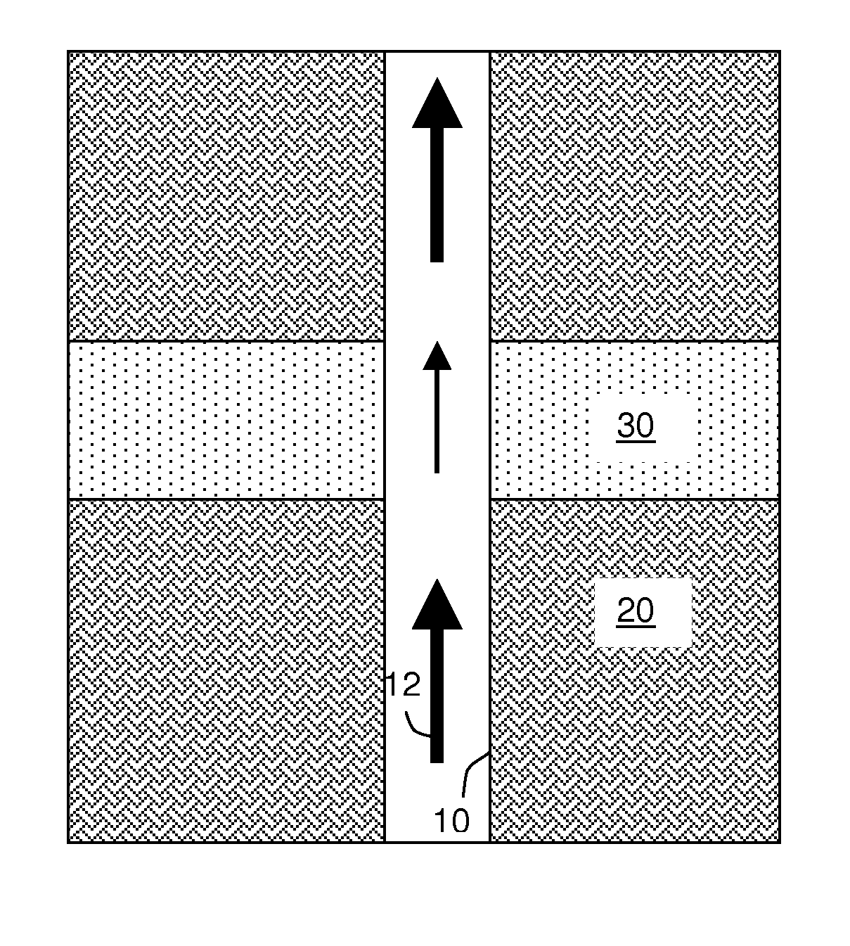
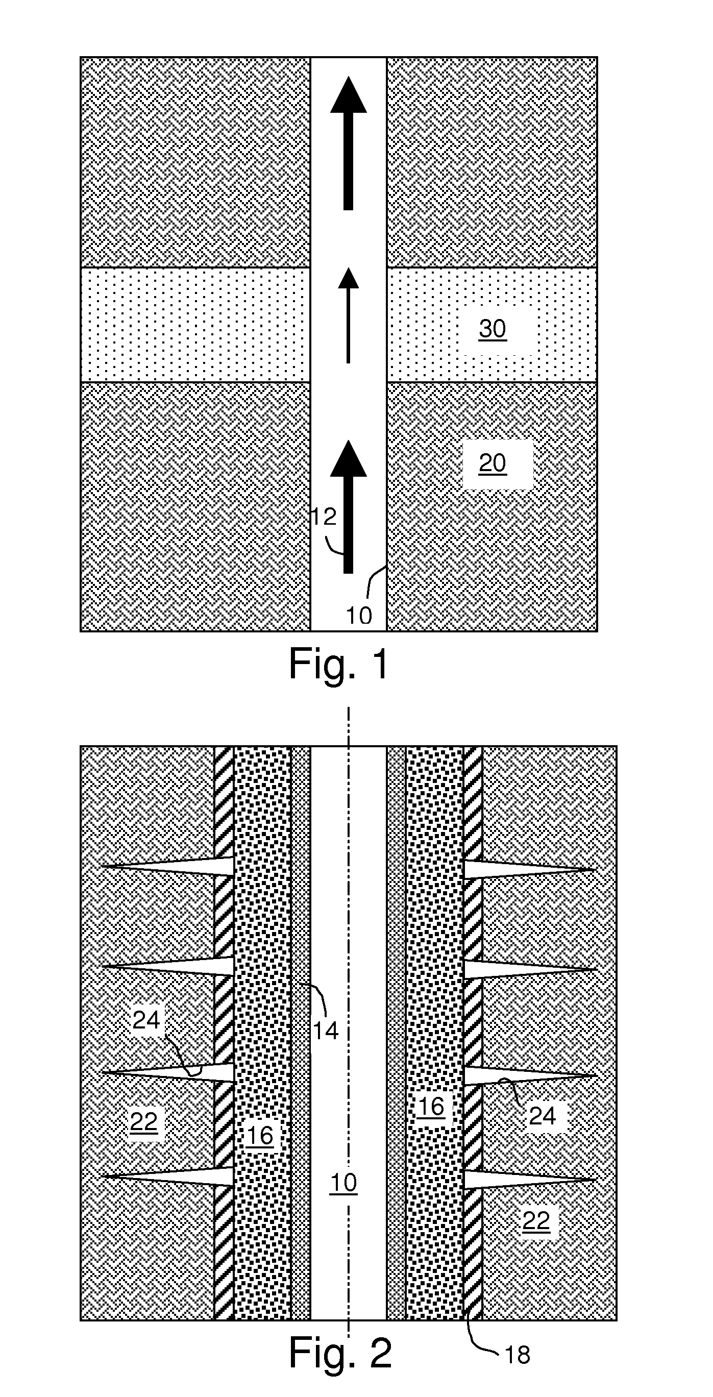
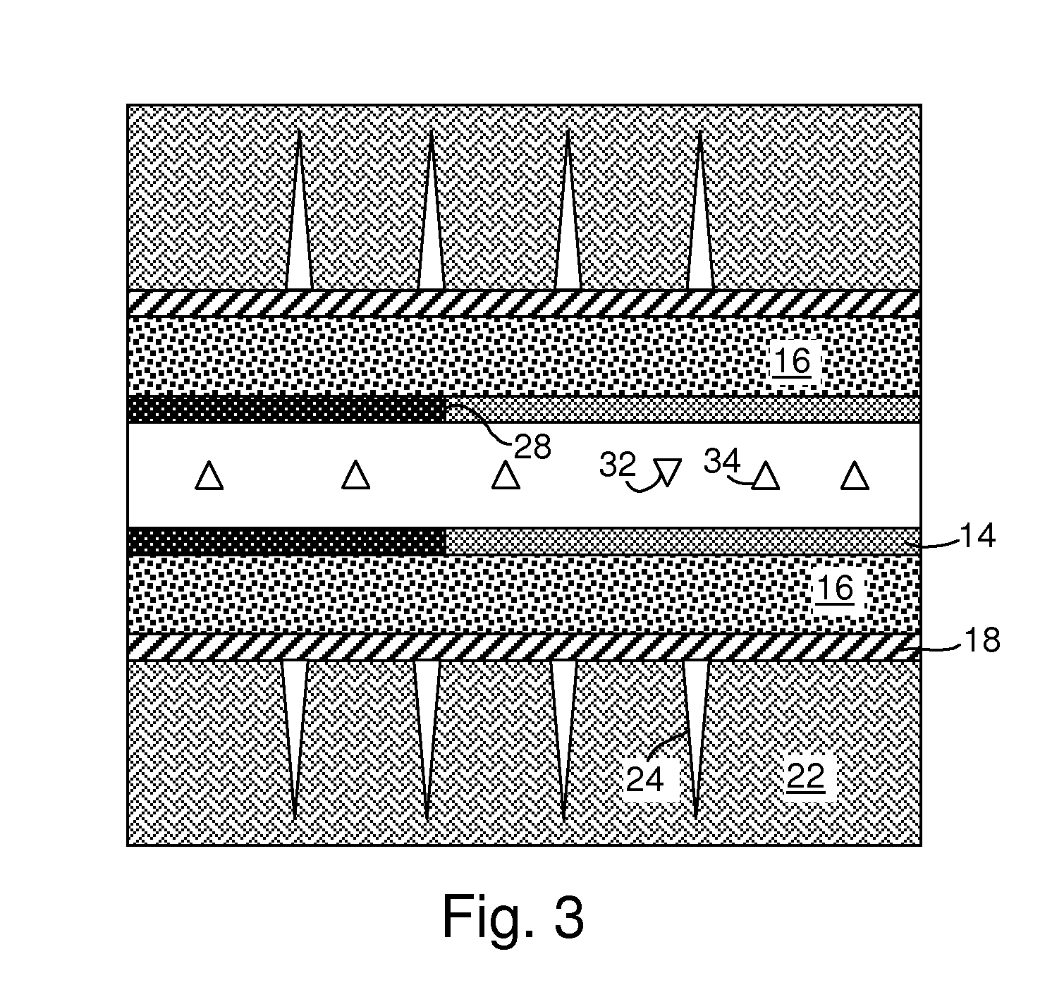
[0020]It will be understood that the use herein of a singular term, such as, but not limited to, “a,” is not intended as limiting of the number of items. Also, the use of relational terms, such as, but not limited to, “top,”“bottom,”“left,”“right,”“upper,”“lower,”“down,”“up,”“side,” and the like are used in the written description for clarity in specific reference to the Figures and are not intended to limit the scope of the invention or the appended claims. Additionally, in this description, the terms “up” and “down”; “upward” and downward”; “upstream” and “downstream”; and other like terms indicating relative positions above or below a given point or element are used in this description to more clearly described some embodiments of the invention. However, when applied to apparatus and methods for use in wells that are deviated or horizontal, such terms may refer to a left to right, right to left, or other relationship as appropriate. Discussion of singular elements can include plu...


PUM


Abstract

A method for monitoring fluid flow through a downhole device, comprises a) providing an acoustic tube wave in fluid in the device; b) measuring the acoustic tube wave after it has passed through the fluid in the device; and c) assessing the permeability of the device by measuring the attenuation of the acoustic signal. Changes in velocity of the acoustic signal may also be measured. The device may be a permeable downhole device such as a sand screen the measurements in step b) are made using a plurality of sensors deployed in the hole. The method may further including the step of cross-correlating a signal received at a first receiver with signals received at additional sensors so as to obtain an effective response as if the signal had been emitted from a source at the position of said first receiver.

Description

CROSS REFERENCE TO RELATED APPLICATIONS[0001]The present application claims priority to U.S. application Ser. No. 61 / 004,877, filed on Nov. 30, 2007, and Ser. No. 61 / 058,944, filed on Jun. 5, 2008, each of which is incorporated herein in its entirety.STATEMENT REGARDING FEDERALLY SPONSORED RESEARCH OR DEVELOPMENT[0002]Not applicable.FIELD OF THE INVENTION[0003]The inventions disclosed and taught herein relate generally to the field of subterranean well monitoring, and more specifically to methods and systems for the real-time acoustic monitoring of completed wells and the surrounding subterranean regions.BACKGROUND OF THE INVENTION[0004]Completions lie at the heart of deepwater production and constitute a large portion of the overall well cost. Great multidisciplinary effort is invested in designing them. This contrasts greatly with the production stage, where little information is available to detect problems, optimize the inflow and prevent expensive work-overs. Sand screen pluggi...

Claims


Application Information

Patent Timeline
Patent Type & Authority Applications(United States)
IPC IPC(8): E21B47/10
CPCE21B47/107E21B43/00G01N15/08G01N29/07G01N29/11G01N2015/084
Inventor BAKULIN, ANDREY VICTOROVICH
Owner SHELL USA INC
Why Eureka
Try Eureka