Oxygen concentrator apparatus and method having variable operation modes

a technology of oxygen concentrator and operating mode, which is applied in the direction of valve operating means/release devices, separation processes, instruments, etc., can solve the problems of reducing the sensitivity of the oxygen concentrator to pressure changes. , to achieve the effect of small radius and increased sensitivity to pressure changes

Active Publication Date: 2011-02-10
INOVA LABS
View PDF102 Cites 49 Cited by
  • Summary
  • Abstract
  • Description
  • Claims
  • Application Information

AI Technical Summary

Benefits of technology

[0011]In some embodiments, the oxygen concentrator may use a dual lumen (including a first tube and a second tube). The first tube may be used to deliver oxygen to the user's nose and the second tube may extend to the entrance of the user's nose to communicate a change in pressure (e.g., from the start of a breath through the user's nose) from the entry of the user's nose to the oxygen concentrator. In some embodiments, the second tube may have a smaller radius than the first tube to allow for increased sensitivity to pressure changes in the second tube.

Problems solved by technology

Usually a specific oxygen flow rate is prescribed (e.g., 1 liter per minute (LPM), 2 LPM, 3 LPM, etc.) Oxygen concentrators used to provide these flow rates may be bulky and heavy making ordinary ambulatory activities with them difficult and impractical.
Portable tanks of medical oxygen may also be heavy and contain limited amounts of oxygen.
Prior art oxygen concentrators may have several limitations.
In addition, the length of the supply tubing to the nasal cannula or mask from the oxygen concentrator may be limited to 6 to 8 feet.
This limitation may be a problem for users using the device in their sleep.
In addition, time, pressure and orifice size are used to determine a volume of air delivered to a user of an oxygen concentrator (however, this measurement technique may not account for pressure fluctuations).

Method used


Image

  • Oxygen concentrator apparatus and method having variable operation modes
  • Oxygen concentrator apparatus and method having variable operation modes
  • Oxygen concentrator apparatus and method having variable operation modes

Examples


Embodiment Construction

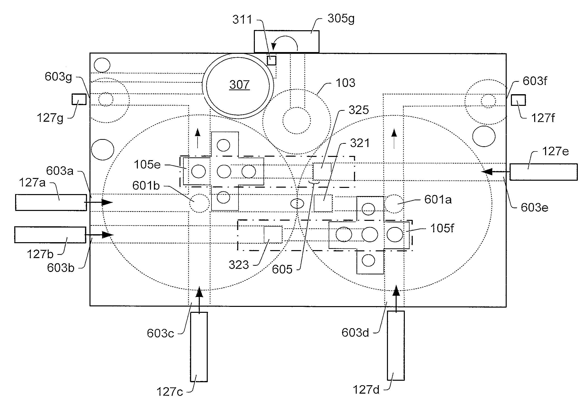
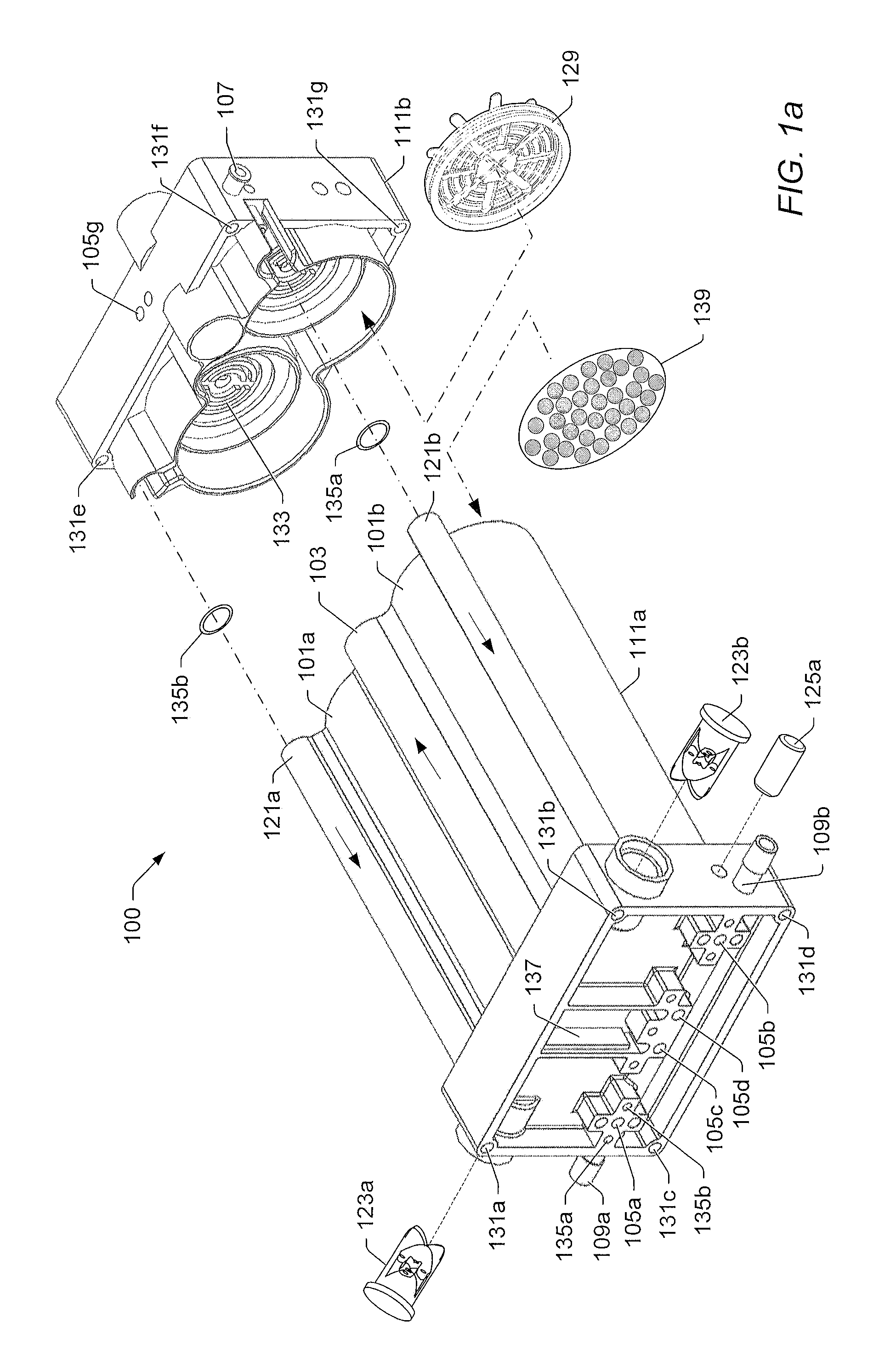
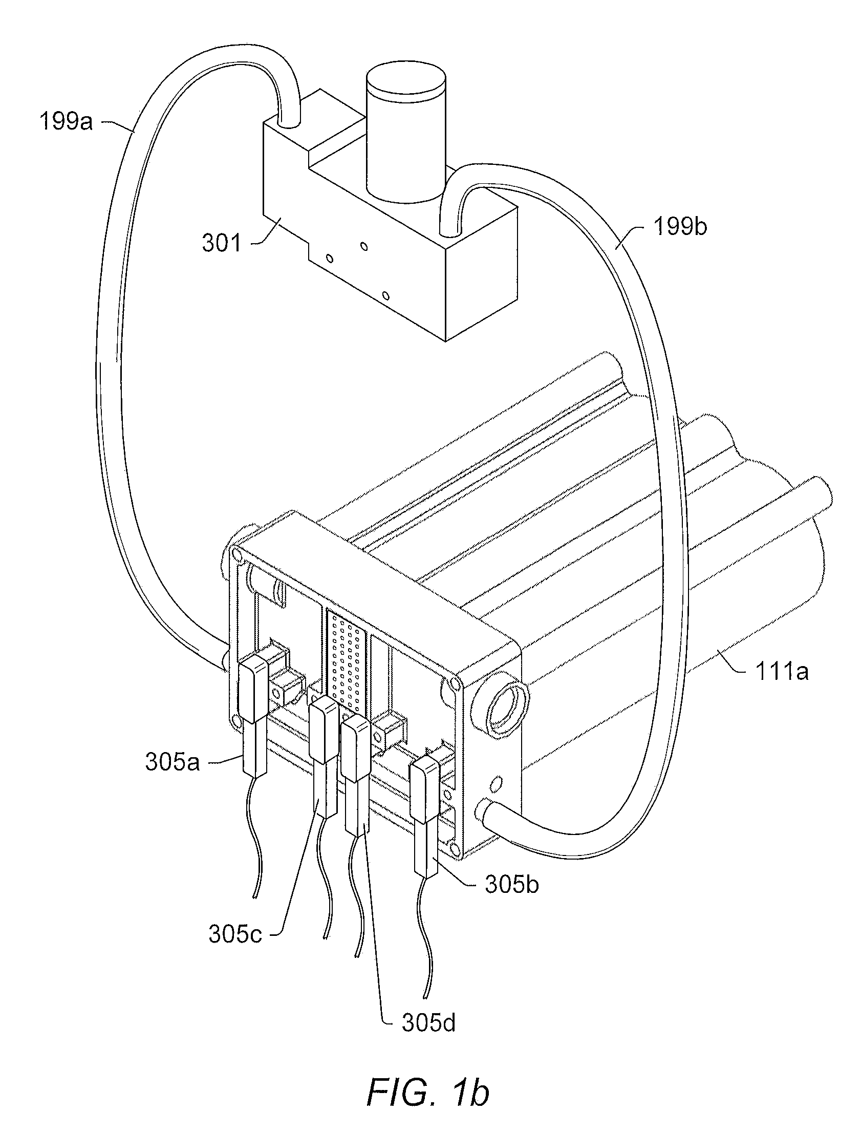
[0046]FIGS. 1a-2b illustrate various views of housing components 111a-b for an oxygen concentrator 100, according to an embodiment. In some embodiments, the oxygen concentrator 100 may concentrate oxygen out of the air to provide supplemental oxygen to a user. The oxygen may be collected from ambient air by pressurizing the ambient air in a canister (e.g., canisters 101a-b) with granules 139 (e.g., molecular sieve granules) such as zeolite 391 (see FIG. 3). Other materials (used instead of or in addition to zeolite 391) may be used. In some embodiments, the air may be pressurized in the canister 101 using one or more compressors 301. In some embodiments, the ambient air may be pressurized in the canisters 101 to a pressure approximately in a range of 13-20 pounds per square inch (psi). Other pressures may also be used (e.g., if a different granule type is used). Under pressure, the nitrogen molecules in the pressurized ambient air may enter the pores of the granules 139 in the canis...


PUM

PropertyMeasurementUnit
lengthaaaaaaaaaa
pressureaaaaaaaaaa
voltageaaaaaaaaaa

Abstract

An oxygen concentrator may rely on a pressure swing adsorption process to produce an oxygen enriched gas stream from canisters filled with granules capable of separation of oxygen from an air stream. The adsorption process uses a cyclical pressurization and venting of the canisters to generate an oxygen enriched gas stream. The oxygen concentrator system may operate in multiple modes, automatically determined or selected by the user, to take into account the different activity levels of the user.

Description

PRIORITY[0001]This application is a Continuation of U.S. patent application Ser. No. 12 / 163,549 entitled “OXYGEN CONCENTRATOR APPARATUS AND METHOD”, filed on Jun. 27, 2008, which claims the benefit of priority of U.S. Provisional Patent Application Ser. No. 60 / 970,371 titled “Oxygen Concentrator Apparatus and Method”, filed on Sep. 6, 2007, both of which are hereby incorporated by reference in its entirety as though fully and completely set forth herein.BACKGROUND[0002]1. Field of the Invention[0003]The present invention relates generally to health equipment and, more specifically, to oxygen concentrators.[0004]2. Description of the Related Art[0005]Patients (e.g., those suffering with diseases such as emphysema, congestive heart failure, acute or chronic pulmonary insufficiency, etc.) may require supplemental oxygen. Other people (e.g., obese individuals) may also require supplemental oxygen, for example, to maintain elevated activity levels. Doctors may prescribe oxygen concentrat...

Claims


Application Information

Patent Timeline
Patent Type & Authority Applications(United States)
IPC IPC(8): A61M16/10A62B7/10
CPCA61M16/0666A61M16/0672A61M2016/0021A61M2016/0024A61M2016/0027A61M2016/0039A61M2016/1025A61M2202/0208A61M2205/17A61M2205/3372A61M2205/3375A61M2205/3553A61M2205/3592A61M2205/42A61M2205/502A61M2205/581A61M2205/583A61M2205/8206A61M2205/8237A61M2209/088B01D53/0446B01D53/0454B01D2253/108B01D2256/12B01D2259/402B01D2259/4533B01D2259/455G01N2291/02881A61M16/0677A61M16/101A61M2202/0266A61M2016/0015A61M16/208A61M16/1055A61M16/0051A61M2205/7518A61M16/0069A61M16/0003A61M2205/52A61M2205/3327A61M2205/18A61M16/10A61M16/107A61M16/024
Inventor WILKINSON, WILLIAM R.WESTERSTEN, ALLAN STENSHOCKLEY, JR., H. DAVID
Owner INOVA LABS
Why Eureka
Try Eureka